
User Manual

5. Controlling the SPC200
5−10
Festo P.BE−S PC200−EN en 0901d
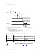
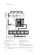
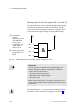
9 8 7 24V
I0.9 I0.8 I0.7
ENABLE STOP
START/
RESET
1)
24V
1
2
3
−
3 7 24V 0V
Q0.4 Q0.7 −
MC_A 24V
READY
0V
−
4
5
6
7
24V
0V
1)
RESET (Program Reset) in conjunction with 0−signal at the STOP input
8
1 Designation on plug X5
2 Input address (I = input)
3 Function
4 Load voltage (can be switched off
separately)
5 Designation on plug X6
6 Output address (Q = output)
7 Function
8 Power supply for outputs (can be
switched off separately as an option)
Fig.5/4: Example of an I/O circuit for the operating mode Start/Stop with operation via
a control panel