
User Manual

Contents and general instructions
XV
Festo P.BE−SPC200−EN en 0901d
Product−specific terms and abbreviations
The following product−specific terms and abbreviations are
used in this manual:
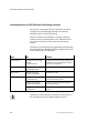
Term/
abbreviation
Meaning
0−signal Input or output supplies 0 V
1−signal Input or output supplies 24 V
Application data Configuration data which describe the conditions of use specified by the
application.
Axis data Configuration data which describe the structure, the features and the com
ponents of the axis used.
Axis interface The measuring system and the proportional directional control valve are
connected to the SPC200 via the axis interface.
Axis interface string All the modules and cables which are each connected to an axis interface
connection of the SPC200.
CP cable Special cable for connecting the various modules to the axis interface string.
F Flags
I Digital input
I/O modules Common term for the modules which provide digital inputs and outputs on
the axis interface string.
I/Os Digital inputs and outputs
Modules Function cards which are inserted in the rack of the SPC200.
PLC/IPC Programmable logic controller/industrial PC
Q Digital output
R Register
String All the modules which are each connected to an axis interface string.