
User Manual

4. Commissioning
4−12
Festo P.BE−S PC200−EN en 0901d
1
0
1
0
1
2
34
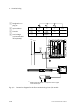
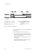
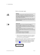
1= 1−signal = 24 V
0= 0−signal = 0 V
1 ENABLE input on the SPC200
2 R EADY output on the S PC200
3 Reaction time max. 10 ms
4 Reaction time of the S PC200:
without stepping motor module:
max. 100 ms
with stepping motor module:
max. 2 s
Fig.4/2: Time diagram of enable signal
The controller is enabled with a 1−signal, providing there are
no system faults.
A 1−signal at the ENABLE input causes the following:
The current position of the axis becomes
the nominal
position i.e. the axis stops in this position under closed−
loop control (controlled stop).
The READY output is automatically set again, see the
following pages.
If the READY output supplies a 1−signal, the program
sequence can be started or continued.