
User Manual

3. Installation
3−65
Festo P.BE−SPC200−EN en 0901d
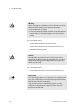
3.6.3 Installing control panel SPC200−MMI−1F
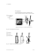
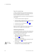
Connect the power supply as shown in the following diagram.
Pin 2: RxD
Pin 3: TxD
Pin 5: SGND
AC
DC
PE
0V
24V
RS232
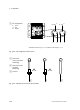
24V
FE
0V
1
2
3
4
1
Control panel SPC200−MMI−1F
2 Power supply (Phoenix Combicon
terminal 3x3.81)
3 RS232 interface
(see Technical Specifications)
4 Functional earth (FE)
Fig.3/30: Connecting the power supply on the control panel
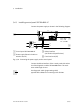
Connect the RS232 interface of the control panel with socket
X4 of the diagnostic module SPC200−MMI−DIAG. The maxi
mum cable length is 10 m.
Use diagnostic cable (programming cable)
type KDI−PPA−3−BU09 for connecting to the SPC200.