
User Manual

3. Installation
3−64
Festo P.BE−S PC200−EN en 0901d
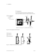
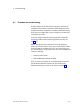
1 Pin assignment:
1: 24 V
3: 0 V
4: Input I
POWER
DIAG
OUTPUT
PNP
01
INPUT/OUTPUT
INPUT01
3 13
1
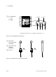
4: Ix.0
1)
4: Ix.1
1)
1)
Module on AIF string 1: x = 1; module on AIF string 2: x = 3
Fig.3/28: Pin assignment of the inputs
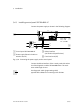
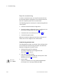
1 Three−wire
sensor (positive−
switching)
2 Two−wire sensor
(positive−
switching)
3 Contact
12 3
Fig.3/29: Example of circuitry of inputs (PNP)