
User Manual

3. Installation
3−62
Festo P.BE−S PC200−EN en 0901d
The I/O function module can be connected as the last module
on the axis interface string. The necessary terminating resis
tor is incorporated in this module.
It provides 2 inputs and 2 outputs for connecting sensors and
actuators directly on the axis. Additional functions, such as
e.g. gripping, lifting, lowering and turning can
be implem
ented with these sensors and actuators.
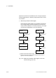
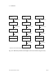
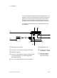
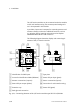
The following diagram shows the display and connecting el
ements of the I/O function module.
POWER
DIAG
OUTPUT
PNP
01
INPUT/OUTPUT
INPUT
01
1
23 4 5 6
7
8
9
aJ
aA
1
Identification for PNP inputs
2 Groove for identification labels (IBS6x10)
3 Actuator connections (outputs)
4 Status LED per output (yellow)
5 Protective cap
6 Earth/ground connection
7 Type plate
8 Status LED per input (green)
9 Sensor connections (inputs)
aJ Connection for axis interface string
aA Status LED (green)
Fig.3/25: Connecting elements of the I/O function module type SPC−FIO−2E/2A−M8