
User Manual

3. Installation
3−51
Festo P.BE−SPC200−EN en 0901d
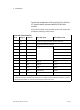
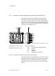
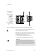
1 Earth/ground
connection
2 Pin assignment:
1: CAN−LOW
(brown)
2: CAN−HIGH
(white)
3: 24 V (yellow)
4: 0 V (green)
5: 24 V load
voltage (grey)
3 Groove with
inserted coding
pin
1
2
3
4
5
1 2
3
Fig.3/20: Pin assignment of the plug for the second axis interface string (X10)
Follow the installation instructions supplied with the cable
when connecting the cable screening.
Depending on the cable used, connect the cable screening
either to the earth connection 1 or to a large surface, com
plying with EMC requirements as follows:
to a
screening plate intended for this purpose
through the cable opening into the control cabinet.
Please note
In order to avoid confusing the connections X10 and X1,
assign different codes to each connection. In order to do
this, push the coding pins supplied into different grooves
in the contact strips. Remove the relevant material on the
plug.