
User Manual
3. Installation
3−42
Festo P.BE−S PC200−EN en 0901d
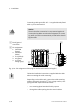
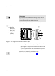
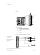
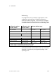
Basic rules If several I/O modules are installed in a rack, observe the
following:
The I/O module inserted on the left next to the power
supply module is the first I/O module. Further I/O mod
ules are counted from left to right.
If a field bus module is not installed, the first I/O module
will
provide five freely programmable inputs, three freely
programmable outputs and I/Os for controlling the
SPC200 (I0.0 ... I0.9 and Q0.0 ... Q0.7). All I/Os of fur ther
I/O modules are freely programmable.
If a field bus module is installed, the address ranges
I0.0... I0.9 and Q0.0 ... Q0.7 are not available. The first
I/O
module then occupies the addresses I2.0 ... I2.9 and
Q2.0 ... Q2.7. Their I/Os are therefore also freely program
mable.
Explanations of the I/O control signals in the relevant operat
ing mode can be found in chapter 5.