
User Manual

3. Installation
3−32
Festo P.BE−S PC200−EN en 0901d
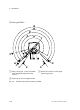
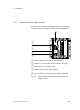
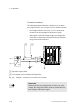
Connection example
The following diagram shows the connection of a common
24V supply for pin 1 (24 L) and pin 2 (24 V). Please note that:
the voltage tolerance of 24 V DC −5/+25 % must be ob
served for the load voltage and electronics supply
with regard to the load voltage supply, the voltage
toler
ances of the components connected to the axis interface
string must also be obser ved.
PE
24L
AC
230V
DC
24V
24V
0V
1 2
1 Separate supply cables
2 Load voltage (can be switched off separately)
Fig.3/9: Example connection of a common 24 V supply
Please note
Switching off the load voltage leads to faults (e.g. under
voltage, AIF string faults) which must be quitted when the
load voltage is switched on again.