
Instruction Manual

3. Installation
3−18
Festo P.BE−CPX−SYS−EN en 0902e
Special features concerning the use of the CPX−CP interface
Note
The CPX−CP interface connects the current rails 0V
el/sen
and 0V
val
of the CPX valve terminal. This means that the
separate circuits for the operating voltage for the electro
nics/sensors (V
el/sen
) and the load supply for the valves
(V
val
) will no longer be effective until the next additional
supply for valves following the CPX−CP interface.
Further information on the power supply for the CPX terminal
in conjunction with the CPX−CP interface can be found in the
manual for the CPX−CP interface in the section Installation"
section Power supply concept −
forming voltage zones."
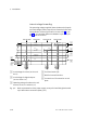
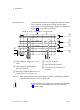
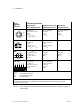
Pin allocation for the alternative connections
Caution
Short circuits can cause damage.
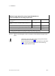
Provide external fuse protection for the system supply and
additional supplies. The permissible current per pin at the
supply is:
7/8" plug, 4−pin: max. 10A
1)
2)
7/8" plug, 5−pin: max. 8A
1)
M18 plug (4−pin): max. 16A
2)
Push−pull plug (5−pin): max. 16A
1)
Limited by the specification of the connected plug con
nector. Values apply for plug connectors from Festo Acces
sories. If using third−par ty products, comply with the appli
cable specifications.
2)
Please note that with a 4−pin system supply via pin
0V", the sum of both currents of the operating and load
voltages flows.