
Instruction Manual

2. Assembly
2−27
Festo P.BE−CPX−SYS−EN en 0902e
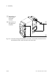
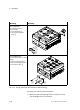
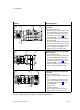
After fitting
· Secure the levers with the aid of the locking screws (see
Fig.2/13, item 6).
2
3
4
5
6
1
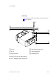
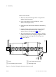
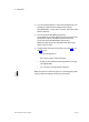
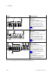
1 Lever
*)
2 O−ring
3 Flat−head screw
4 Self−adhesive rubber foot
5 Clamping elements
6 Retaining screw
*) Different lever lengths with MIDI and MAXI
Fig.2/13: Fitting the H−rail clamping unit