
Instruction Manual

2. Assembly
2−24
Festo P.BE−CPX−SYS−EN en 0902e
Proceed as follows:
1. Make sure that the fastening surface can support the
weight of the CPX terminal.
2. Fit the H−rail (support rail EN 60715 − 35x7.5; width
35mm, height 7.5 mm).
Make sure there is sufficient space to connect the com
pressed air supply tubing.
3. Fasten the H−rail to the mounting surface at intervals
of
approx. every 100 mm.
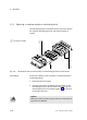
4. Fit an H−rail clamping unit to both the left and the right−
hand end plates and the pneumatic interface of the CPX
terminal.
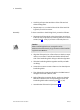
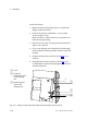
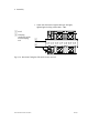
5. Hang the CPX terminal onto the H−rail (see Fig.2/11,
arrow A).
6. Swing the CPX terminal onto the H−rail (see Fig.2/11,
arrow B). Make sure that the clamping
element lies hori
zontally to the H−rail.
1 H−rail
2 Clamping
component of the
H−rail clamping
unit
3 Retaining screw
of the H−rail
clamping unit
1
A
B
2
3
Fig.2/11: Fitting a CPX terminal (here with CPA pneumatics) onto an H−rail