
Instruction Manual

C. General information on parametrisation
C−24
Festo P.BE−CPX−SYS−EN en 0902e
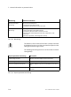
Monitoring Reaction to activation
Module parameters
Monitoring
A fault on the module will be:
Forwarded to the CPX bus node
Displayed by the module common error LED
System parameters
Monitoring
A fault registered by the module will be:
Sent to the higher−order fieldbus master
Displayed by the red SF−LED on the CFX bus node
Entered in the module diagnostic data and, if applicable, in the
status bits
Entered, if applicable, in the diagnostic memory
Tab.C/8: Monitoring
The behaviour of the channel fault LED is normally controlled
by hardware functions and does not therefore depend on the
setting of the monitoring functions.
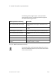
The following monitoring functions can be activated or deacti
vated globally:
System parameter monitoring
Description
Undervoltage of valves Monitors the load voltage supply for the valves
Undervoltage of outputs Monitors the load voltage supply for the outputs
Short circuit/overload of outputs Monitors whether outputs are overloaded or short circui
ted
Short circuit/overload, sensor supply Monitors whether sensor supply is overloaded or short
circuited
Tab.C/9: System parameter monitoring