
Instruction Manual

5. Diagnostics and error handling
5−9
Festo P.BE−CPX−SYS−EN en 0902e
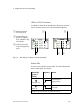
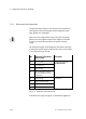
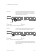
LEDS on CPX I/O modules
In addition to the module−specific LEDs, all electric modules
have a module common error LED for module diagnosis.
1 Module common
error LED (red)
2 Status LEDs (e.g.
green for digital in
puts, yellow for digi
tal outputs)
3 Channel error LED
(e.g. with digital out
puts)
0
1
2
3
8
DI
4
5
6
7
1 1
2
0
1
2
3
4
DO
32
Fig.5/3: LED display of electric modules (example)
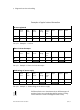
Status LEDs
There is a status LED for each channel. This LED indicates the
status of the signal. This means:
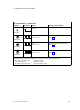
Status LED
(green or
yellow)
Sequence Status
LED lights up
1)
ON
OFF
Channel logical 1
(signal present)
LED is off
ON
OFF
Channel logical 0
(no signal)
1) Lights up green for inputs and yellow for outputs