
Manual

CLR−...
Festo CLR−... 0912d English
27
Pneumatic installation
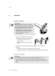
Please note
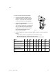
The clamping finger from Festo matches optimally the CLR−... and does not
require any air restriction.
S Note that if user−made clamping fingers are used, the mass moment of inertia
must be calculated.
A higher mass moment of inertia than that specified for the clamping finger
set from Festo requires a reduction
in the stroke time of the CLR−... by the use
of one−way flow control valves.
The dimensions of the cone and the diagrams for determining the stroke time
as a factor of the mass moment of inertia can be found in the Festo cata
logue.
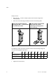
S Remove the adhesive labels on the compressed
air connections.
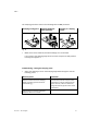
S Check to see if accessories are required as shown in the following table.
Type
Designation Function
HGL−... Non−return valves with
closed−loop control
If there is a pressure falure, the pressure in
the piston chamber will be retained.
GRLA−... /
GRLZ−...
One−way flow control
valves
The piston speed can be modified.
VZS−... Compressed air reservoir Fluctuations in pressure will be reduced in
the downstream−switched compressed air
string.
Fig.15
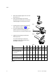
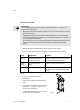
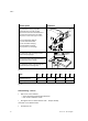
S Use short tubing lines for your
application.
Short lines optimize the pressurisation
time.
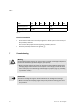
S Screw the one−way flow control valves of
type GRLZ−... or GRLA−... into the com
pressed air connections.
S Connect the tubing of the CLR−... to the
compressed air connections.
Fig.16