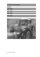
OPERATING MANUAL FENDT 916 Vario 920 Vario 924 Vario 926 Vario 930 Vario 930.000.000.
Vehicle type ............................. Chassis No. ............................. After-Sales Service Vehicle delivery Vehicle pre-delivery inspection by the Service Workshop For information, technical date etc. refer to Service Schedule. Check oil level, top up if necessary. Engine, transmission, axle drives, front axle differential, hub drives, front PTO, lift shaft lubrication. Fill the hydraulic system with additional oil for external consumers as per customer order.
OPERATING MANUAL FENDT 916 Vario From chassis number 916 .. 7001 FENDT 920 Vario From chassis number 920 .. 7001 FENDT 924 Vario From chassis number 924 .. 7001 FENDT 926 Vario From chassis number 926 .. 7001 FENDT 930 Vario From chassis number 930 .. 2001 ETManufacturer ETAuthor AGCO GmbH Maschinen und Schlepperfabrik D-87616 Marktoberdorf / Bavaria / Germany Telephone +49 8342 77-0 Facsimile +49 8342 77-222 © PSD / Ko - SG 10.
Marking of places that affect your safety Customer-notes Text-module Dear Customer, Make sure that any other users have read all the safety instructions as well. The various levels of safety instructions can be distinguished as follows: Please note the following: ● Before using the tractor, carefully read through this Manual to familiarize yourself with all operating controls and their functions before you begin work. This also applies to the operating instructions of the implement manufacturer.
NUMERICAL INDEX SAFETY INSTRUCTIONS...............9 OPERATION....................................14 1. 1.1 Driver seat ................................................14 Super deluxe seat ......................................14 2. 2.1 2.2 2.3 2.4 2.5 2.6 2.7 2.8 2.9 2.10 2.11 2.12 2.13 2.14 2.15 2.16 2.17 2.18 2.19 Display instruments and operating controls.....................................................15 Front controls .............................................15 Glow and starter switch.......
NUMERICAL INDEX 18.7 18.8 Electronic power lift control / double action operation (EPC/DA)...................................84 Implement socket.......................................85 19. 19.1 19.2 19.3 19.4 Three-point link ........................................85 Lower links .................................................85 Extendable lifting struts..............................86 Mechanical side locks ................................87 Top link ...................................................
NUMERICAL INDEX 9. Front PTO ...............................................149 10. 10.1 10.2 10.3 Transmission and axle drives...............149 Changing the transmission oil..................149 Checking the transmission oil level..........150 Changing the oil in the axle drives ...........151 11. 11.1 11.2 11.3 Four-wheel drive axle ............................151 Changing the oil in the front axle differential gear ........................................
NUMERICAL INDEX 8
SAFETY INSTRUCTIONS Safety and accident prevention regulations WARNING: Before every operation, check the tractor for road worthiness and operational safety. Carefully read the Manual and observe all safety instructions. Safety signs on the machine must be replaced if damaged or lost. General safety and accident prevention regulations Driving the tractor 1. Driving speed must always be adapted to the current situation. Avoid sudden cornering when driving uphill or downhill, or across gradients.
SAFETY INSTRUCTIONS Leaving the tractor 4. When the front loader is raised, the risk of the tractor tipping over is greater, and the braking effect at the rear axle may also be reduced. Adapt your driving style and ensure adequate ballasting at the rear. For additional loading, we recommend attaching the Fendt 870 kg additional weight at the three-point link - fit wheel weights and fill the tyres if necessary. 5. Keep a safe distance from high-voltage cables. 6.
SAFETY INSTRUCTIONS Maintenance Text-module Advice for front loader maintenance: 1. Before undertaking maintenance work, lower the front loader to the ground, switch off the engine and remove the ignition key. 2. If the pipe fracture protection has engaged, support the load before starting repairs, and slowly retract the cylinder. 3. Hydraulic hoses deteriorate with age. Check the condition of hydraulic hoses at regular intervals, and replace them in good time. 4.
SAFETY INSTRUCTIONS Location of safety signs Operation_Pic_number:1 Operation_Pic_number:1 Fig.4 On the left and right rear mudguards beside the lifting gear control. Operation_Pic_number:1 Fig.1 Inside the cab on the right. Operation_Pic_number:1 Fig.2 Fig.5 Inside the cab on the right. At left front of hydraulic cylinder of front axle suspension. Operation_Pic_number:1 Operation_Pic_number:1 Fig.3 On the right rear mudguard. Fig.6 On pressure reservoir of front axle suspension.
SAFETY INSTRUCTIONS Operation_Pic_number:1 Fig.7 Inside the cab on left. Operation_Pic_number:1 Fig.8 Inside the cab, on the cover of the emergency operation controls. Operation_Pic_number:1 Fig.9 On the front loader forks, left and right. Operation_Pic_number:1 Fig.10 Inside the cab, on the left, on the transverse beam of the front windscreen.
OPERATION 1. Driver seat WARNING: Never adjust the seat while the tractor is moving (risk of accident). If a seat belt is available, always attach it. 1.1 Super deluxe seat Operation_Pic_number:1 Fig.1 Text-module A B C D E F G H I J K L = Automatic weight and height adjustment. = Swivel mechanism. = Longitudinal adjustment. = Backrest adjustment. = Lumbar support (curvature), pneumatic operation. = Seat bolster (depth adjustment). = Seat bolster (tilt adjustment). = Horizontal springing (on/off).
OPERATION 2. Display instruments and operating controls 2.1 Front controls Operation_Pic_number:1 Fig.2 Text-module A B C D E F G H I K L = = = = = = = = = = = Hand brake Clutch pedal Steering wheel adjustment and quick reverse. Heater and fan controls (see also OPERATION Section 3). Combination switch Heater starter switch Multi-function armrest Accelerator pedal Brake pedals Emergency operation controls (under the cover).
OPERATION 2.2 Glow and starter switch 2.4 Steering wheel adjustment Operation_Pic_number:1 WARNING: Never adjust the steering wheel while the tractor is moving! Operation_Pic_number:1 Fig.3 Text-module 0 I II = Ignition off, key can be removed. = General ignition, key cannot be removed + preheating (automatic). = Starting + ignition. 2.3 Combination switch Operation_Pic_number:1 Fig.5 Text-module ● Pull up lever and adjust steering wheel to the desired position (see also OPERATION Section 16). 2.
OPERATION 2.6 Dashboard Operation_Pic_number:1 Fig.7 Text-module A B C D E F G Text-module = = = = = = = Multiple display Indication of fluid levels Operating status display Indicator lamps Lights including side lights Hazard warning flasher switch Key pad for on-board computer (also see OPERATION Section 26). H J K L M = Key pad for rpm indicators (also see OPERATION Section 2.8). = Key pad for speed display (also see OPERATION Section 2.8).
OPERATION 2.7 Indication of fluid levels 2.8 Operating status display Operation_Pic_number:1 Operation_Pic_number:1 Fig.8 Fig.9 Text-module A B C D E Text-module = Fuel supply = Engine temperature When the bar indicators reach the red zone, relieve the engine of load immediately and allow to cool down for about 2 minutes at 1000 rpm, then turn the engine off.
OPERATION 2.9 Multiple display 2.10 Operating controls, right For warnings, fault messages and on-board computer functions. Operation_Pic_number:1 Operation_Pic_number:1 Fig.11 Text-module A B Fig.10 In the basic display, the clock (A) and operating hours (B) are indicated. This is interrupted for warnings, fault messages and on-board computer functions. C D E 19 = Hand throttle = Behind the moulding, M10 threaded holes for fixing additional equipment, e.g.
OPERATION 2.11 Multi-function armrest Operation_Pic_number:1 Fig.12 Text-module A B C D E F G H I J K L = = = = = = = = = = = = M N O P R = = = = = Joystick (see also OPERATION Section 7.1). Acceleration rate selection (see also OPERATION Section 7.3). Activating button on the back of the joystick. EPC PTO automatic mode stop button (see also OPERATION Section 14.2). Floating position of hydraulic valve, green or blue (see also OPERATION Section 17.3).
OPERATION 2.12 Operating console, right side Operation_Pic_number:1 Fig.13 Text-module A B G H O P = Vario terminal (see also OPERATION Section 2.13). = Additional headlamps (on front of roof; can be switched on only when the headlamps are on these then go off). = Depth regulation rear power lift. = Quick lift rear power lift. = Comfort front power lift depth control. = Quick Lift, comfort front power lift.
OPERATION 2.13 Vario terminal Text-module 4-WD (see also OPERATION Section 11). 4-WD 100%; ON/OFF Operation_Pic_number:1 4-WD automatic mode ON/OFF Text-module Differential lock (see also OPERATION Section 12). Differential lock 100 % ON/OFF Differential lock automatic mode ON/ OFF Fig.14 Text-module Text-module Front axle suspension (also see OPERATION Section 13).
OPERATION First main menu Operation_Pic_number:1 Fig.15 Text-module Pressing keys (F1 - F5) gives access to the following functions.
OPERATION Second main menu Third main menu Operation_Pic_number:1 Operation_Pic_number:1 Fig.16 Fig.17 Text-module Text-module Pressing keys (F1 - F5) gives access to the following functions. F1 = On-board computer F2 = Store terminal settings F3 = Implement control F4 = Variotronic Ti F5 = Switch to third menu Pressing keys (F1 - F5) gives access to the following functions. F1 = Camera image (optional). F2 = Camera image mirrored (optional).
OPERATION Adjusting screen brightness and contrast Operation_Pic_number:1 The brightness of the Vario terminal is automatically adjusted. Dimming can be adjusted steplesssly if necessary. Operation_Pic_number:1 Fig.19 ● Rotary control (P1) for setting degree of dimming. Bar indicators: right left Fig.18 = no dimming. = max. dimming. Text-module Any setting between the two positions is possible. It is set in the third main menu ● Press key F4.
OPERATION 2.14 Camera function 2.15 Quick Jump Text-module Text-module (optional). This function allows a preset menu page to be selected directly from the first menu level. Turning the rotary control (P1 - P3) slightly, selects the preset menu page. Operation_Pic_number:1 Press ESC key ● Display returns to first main menu. Selecting menu pages Operation_Pic_number:1 Fig.20 ● Press the F1 or F2 key. Following sub-menu for terminal settings appears. Operation_Pic_number:1 Fig.22 ● Press F3 key.
OPERATION Selection of the jump menu items On-board computer 1- 4 The jump menu items that can be selected, depend on the tractor equipment, e.g. if no front power lift is fitted, this jump menu item is not shown in the selection list. Front power lift Load implement settings Only possible if Teach In and the automatic modes for the power lift and PTO are not active. Rear power lift Save implement settings Only possible if Teach In and the automatic modes for the power lift and PTO are not active.
OPERATION 2.16 Cab top section, front 2.17 Cab top right side Operation_Pic_number:1 Operation_Pic_number:1 Fig.24 Fig.25 Text-module A B C Text-module = Adjustable air nozzles = Cab lighting = Right-hand console lights A B C = Auxiliary ventilation (see also OPERATION Section 3.2). = Air conditioning ON/OFF and temperature control switch (see also OPERATION Section 3.3). = Space for radio installation, blanking panel. Connectors behind the panel are fitted as standard.
OPERATION 2.18 Power outlets Operation_Pic_number:1 Operation_Pic_number:1 Fig.28 A Fig.26 = Trailer socket. Operation_Pic_number:1 Text-module A B C D E F = = = = = 25 A constant current socket. 10 A socket. Implement socket. Socket (blue) for external pulse counter. LBS-ISO socket (optional) short circuit plug must remain in place due to feedback. = Camera socket (optional). Pin - attribution LBS-ISO implement socket cabin Operation_Pic_number:1 Fig.
OPERATION Pin - attribution LBS-ISO implement socket rear and front ABS socket (A) Operation_Pic_number:1 Operation_Pic_number:1 Fig.32 Fig.31 1 2 3 4 5 A = LBS-ISO socket for the mounted implement. B = LBS-ISO connector for the mounted implement. Pin 1 = Earth 60A. Pin 2 = Earth 25A. Pin 3 = 60A power supply. Pin 4 = 25A power supply for implement electronics. Pin 5 = Control signal for switching the end system, bridged with pin 4 in the connector. Pin 6 = CAN-EN. Pin 7 = CAN GND. Pin 8 = CAN High.
OPERATION 3. Heating and ventilation 2.19 Reset function Operation_Pic_number:1 3.1 Heater with 3-speed blower Operation_Pic_number:1 Fig.35 Reset - initiate function. ● Press clutch pedal. ● Press push button (A). Fig.36 The heating depends on the water temperature. To end Reset function. ● Stop the tractor. ● Switch ignition OFF/ON. Switch on fan (control knob A). Fan off. Text-module When a reset is made, the following are restored to their basic settings.
OPERATION 3.2 Auxiliary ventilation in cab roof 3.3 Air conditioning WARNING: All repair and maintenance work must be carried out by qualified personnel only. Avoid all contact with liquid coolant. If accidentally splashed in the eyes, seek medical advice immediately. No welding should be carried out on or near any parts of the air conditioning systems! Risk of poisoning! Maximum ambient temperature for coolant 80 °C. Check the V-belt only while the engine is stopped. Attach the protective grille again.
OPERATION 4. Rearwiew mirror 5. Start-up 5.1 Daily check CAUTION: Before driving the tractor and starting work, adjust the mirror to guarantee a clear view of the road and of the working area to the rear. Text-module Tractor must be in proper working condition. Operation_Pic_number:1 Pull-out rearview mirror Operation_Pic_number:1 Fig.40 ● Check fuel level. If necessary, top up through filler neck (A). Top up with fuel after the day's operation to avoid build-up of condensation.
OPERATION 6. Starting and stopping the engine 5.2 Cold weather operation Text-module Keep battery well charged; fill with winter fuel. At temperatures below -12 °C, add flow improver or up to 30% petroleum. Top up engine oil with HD-SAE 10W; Antifreeze in coolant 35 - 50 vol.-%. DANGER: Start the engine from the driver seat only. Never short circuit the battery. Never leave the engine running in a confined space! Do not use priming fuel (e.g. Startpilot)! Engine warmer (optional).
OPERATION Tractor in driving mode 6.2 Starting the engine If the tractor moves off immediately after it is started, the following picture appears. IMPORTANT: Do not start or operate the tractor without a battery. This could destroy the alternator. Pay attention to warnings and fault messages. If necessary, switch off the engine immediately. Operation_Pic_number:1 ● Apply the hand brake. ● Depress clutch pedal (starting inhibit is deactivated). ● Switch off PTOs and other drives.
OPERATION NOTE: The flame start control unit detects faults in the flame starting system; these faults are indicated through various flash codes displayed on the preheating indicator (see FAULTS AND REMEDIAL ACTIONS Section 4.1). Jump starting a partially discharged battery with another battery. ● Connect jump leads to the assisting battery in sequence (1-4). ● Start engine immediately. ● Once the engine is running, disconnect the cables in reverse order. 6.3 Jump starting If the attempt is unsuccessful.
OPERATION 7. Vario transmission 6.4 Tow-starting 7.1 Joystick WARNING: Tow-starting is not possible! Operation_Pic_number:1 6.5 Stopping the engine ● Turn ignition key to position 0. Text-module NOTE: After operating at full load, do not stop the engine immediately but allow it to cool down for about 2 minutes at about 1000 rpm. 6.6 Stopping and immobilising the tractor Fig.
OPERATION Setting acceleration rate I ETNum-list Indicators when Neutral position is disengaged. 1. LED (N1) is not lit. 2. Direction of travel indicator (C) are lit. 3. ACTIVE symbol indicator (E) on the multiple display. 4. Warning light (F) flashes. Operation_Pic_number:1 ETNum-list Fig.51 7.3 Selecting acceleration rates Text-module Procedure: Press key, graphic (K) is displayed. Operation_Pic_number:1 Press one of the keys repeatedly until symbol (X) flashes.
OPERATION 7.4 Driving mode selector Switching when tractor stationary ● Select Neutral position or ● operate clutch pedal. ● Select the desired mode. WARNING: When selecting driving mode, tractive power is interrupted. Do not use on slopes (uphill or downhill). Text-module Selecting driving mode I or II while travelling Operation_Pic_number:1 Driving mode selection is not possible if: ● Neutral position is engaged. ● Transmission oil temperature below 10°C. ● Engine brake actuated.
OPERATION 7.5 Driving the tractor Turboclutch The transmission control includes a turboclutch function. This allows the tractor to be stopped with the accelerator pedal. WARNING: Always engage the gears when travelling downhill. Do not select neutral. At engine speeds over 2600 rpm, the transmission ratio is no longer reduced; to reduce speed, apply the brake. This means: 1. No engine stalling under difficult conditions. 2. No wheel spinning. 3. Full power transmission from approx. 1,250 rpm engine speed.
OPERATION Driving off using the turboclutch function Clutch pedal For connecting implements, the tractor can be controlled for gradual movements with the clutch pedal. In sudden emergencies, the tractor can be stopped by pressing the clutch and brake pedals. ● Setting the engine idle speed. ● Apply the brake. ● Press activating button and use the joystick to select the desired direction of travel. ● Release the brake and start off by accelerating slightly.
OPERATION 7.6 Changing direction of travel The tractor slows to a standstill. When the button (A) is released, the tractor continues in the previous travel direction and with the previous transmission ratio. The tractor slows to a standstill, then accelerates in the desired direction until the previous transmission ratio is reached. Changing the direction of travel using the joystick The change of direction may be activated by: - with the button on the steering wheel adjustment. - with the joystick.
OPERATION 7.7 Programmed changes of travel direction Operation_Pic_number:1 Text-module NOTE: The set values are only reached at an engine speed of 1800 rpm. Text-module Using the control terminal, a forward speed and a reverse speed can be pre-programmed. Operation_Pic_number:1 Fig.60 The set speeds are indicated by the indicators (A and B). (C) shows actual speed; below 0.5 km/h, the values change from km/h to m/h. Indicator from 100 m/h to 500 m/h.
OPERATION 7.8 Cruise control Actuating the stored speed Operation_Pic_number:1 NOTE: Tempomat cruise control only possible at an engine speed above 1,300 rpm. With cruise control, current speed is maintained without storing. In addition, two speeds can be stored to allow the tractor system to be configured for two different situations, such as field work and road travel. Once stored, the cruise control actuates one of the stored speeds.
OPERATION Operation_Pic_number:1 Operation_Pic_number:1 Fig.66 Fig.64 Text-module Text-module Stored speeds are shown on the displays (A and B). ● Turn rotary switch (P2) to set speed in memory 1 (indicator A). ● Turn rotary switch (P3) to set speed in memory 2 (indicator B). ● Accelerate to the desired speed. ● Move the joystick briefly to the right (away from driver seat). Indicator lamp (A) is lit, speed is displayed for 3 seconds on the multiple display (B).
OPERATION 7.9 Load limit control Actuating the preselected speed Operation_Pic_number:1 The load limit control is activated automatically if engine speed drops under load. To do this, the tractor automatically uses the transmission control to reduce the vehicle speed so that engine speed does not drop any further. Setting load limit control Operation_Pic_number:1 Fig.68 Text-module ● While the tractor is moving, move the joystick briefly to the right (away from driver seat).
OPERATION 7.10 Storing engine speeds Stored engine speeds are indicated on the displays (A and B). Two engine speeds can be stored using rotary controls (P1/P2) on the Vario terminal. e.g. Speed 1 working speed - full throttle. e.g. Speed 2 standing speed - idle. NOTE: The maximum engine speed that can be set is the engine limit speed. The minimum engine speed that can be set is the idle speed. The value set can be exceeded with the accelerator.
OPERATION 8. Fuel consumption measurement Operation_Pic_number:1 (also refer to OPERATION Section 27.4). 8.1 Activating fuel consumption measurement Operation_Pic_number:1 Fig.75 ● Indicator (A) appears on the Vario terminal, indicating active stored engine speed. Text-module Engine speed storing is terminated if one of following conditions is present. 1. Speed over 18 km/h and foot brake is operated. 2. Speed over 18 km/h and engine brake is operated. 3. Call-up buttons are activated again. 4.
OPERATION 9. Tractor Management System (TMS) Operation_Pic_number:1 Text-module MODE 1 Joystick - engine management system off The transmission ratio is set with the joystick, the engine speed is set with the accelerator. Text-module MODE 2 Joystick - engine management system on Driving speed is set with the joystick; the engine speed and transmission ratio are set automatically. Fig.79 A B C D = Current fuel consumption. = Average fuel consumption. Measurement at tractor START or Press button (F3).
OPERATION 9.1 Engine management system 9.2 Accelerator mode Activating the accelerator pedal function CAUTION: If engine management is active, the engine speed can increase to maximum engine speed. Operation_Pic_number:1 NOTE: Engine speeds settings made with the hand throttle potentiometer can be exceeded, but speed will not go below the set speed. Text-module NOTE: If the TMS is active, the Tempomat cruise control function has no engine speed limit (e.g.
OPERATION Selecting direction of travel Decelerating with the joystick Operation_Pic_number:1 ● ● ● ● Operation_Pic_number:1 Fig.85 Fig.83 Select direction of travel with switch (A). Selected direction indicator (B) flashes. Start off with the accelerator pedal. Selected travel direction indicator (B) is lit. In accelerator pedal mode, the tractor can also be slowed down with the joystick. Move the joystick in the direction opposite to the current direction of travel.
OPERATION Operation_Pic_number:1 Engine control range active while driving or when front/rear PTO is engaged or when a hydraulic valve is actuated or when lowering front/rear power lift. Engine control range active when a front/rear PTO is engaged or when a hydraulic valve is actuated or when lowering front/rear power lift. Engine control range active when a hydraulic valve is actuated or when lowering front/rear power lift. Fig.
OPERATION 10. PTO DANGER: Switch off the engine before attaching or removing drive shaft, and before cleaning, servicing or repairing PTO-driven implements. Always wait for the implement to come to a complete standstill! Do not operate the PTO before all safety devices are in place. Observe the specified pipe overlap requirements for the drive shaft. During PTO operation make sure no-one remains in the hazard zone! When operating with overrunning implements, use a drive shaft with overrunning clutch. 10.
OPERATION 10.2 Engaging and disengaging rear PTO Selecting PTO speed Operation_Pic_number:1 DANGER: Before engaging PTO, make sure no-one remains in the implement’s hazard zone. The selected PTO speed must be in accordance the permitted implement speed. Operation_Pic_number:1 Fig.92 ● Select the desired PTO speed with one of the following buttons. PTO 540 Economy PTO (750) PTO 1000 Fig.93 The rear PTO can be engaged/disengaged using the button (A).
OPERATION 10.3 Front PTO External operation Operation_Pic_number:1 Text-module (optional). DANGER: After operating the front PTO, switch off the season selection and put the protective sleeve back on the PTO stub shaft. PTO shaft protection sleeve Operation_Pic_number:1 Fig.94 ● Press button (arrowed) on the right or left of the rear lamp. Text-module Safety lock The PTO rotates only as long as the button (arrowed) is pressed.
OPERATION 10.4 Engaging and disengaging front PTO 10.5 Calibrating rear and front PTO coupling DANGER: Before engaging PTO, make sure no-one remains in the implement’s hazard zone. DANGER: During calibration, PTO may rotate slightly. Follow all safety procedures. Operation_Pic_number:1 The PTO clutch is adjusted to adapt the engage process to the implement concerned, e.g. implements that require high initial power to start.
OPERATION Press one of the keys until desired digit appears. Press key. The next image appears. Input code 7034 for front PTO. Storing with the button. Once the last number has been saved, the following screen appears. Select any PTO speed and engage rear PTO. Press one of the keys until desired digit appears. Storing with the button. Once the last number has been saved, the following screen appears. Engage front PTO.
OPERATION 11. Four wheel drive (4-WD) 12. Differential lock DANGER: Do not use on normal roads or when cornering. Maximum speed 20 km/h. Do not operate steering clutch brake. Front-wheel drive can be engaged or disengaged under load. To avoid unnecessary noise level and excessive tyre wear, do not use front-wheel drive for ordinary road travel. It may however become useful to engage it on difficult road surfaces or in conditions of ice and snow. Operation_Pic_number:1 Operation_Pic_number:1 Fig.
OPERATION 13. Front axle suspension Suspension OFF (locked). Tractor body is lowered to the stop at the front axle. DANGER: When the tractor is stationary, raising or lowering the tractor body is dangerous for people in the vicinity of the front axle. Suspension ON (level control). With the tractor stopped: If the button is pressed for more than 3 seconds, the body continues to rise through the total suspension range, as long as the button remains pressed. Only when speed exceeds 2 km/h.
OPERATION 14. Power lift and PTO automatic mode Using automatic mode Operation_Pic_number:1 14.1 Power lift automatic mode Automatic mode allows the control of the rear and front power lift to be transferred to the buttons on the joystick. If the basic settings are not suitable, any setting can be selected with the Variotronic TI. Activating the automatic function Operation_Pic_number:1 Fig.103 ● Button (A1), the front power lift goes into 'Control' mode.
OPERATION 14.2 PTO automatic mode Using automatic mode Operation_Pic_number:1 Allows the control of rear and front PTOs to be transferred to the buttons on the joystick. Activating the automatic function Operation_Pic_number:1 Fig.105 Text-module ● ● ● ● ● Fig.104 ● Selecting PTO speed for rear PTO, (see OPERATION Section 10.1). Button (J), rear PTO automatic mode ON/OFF. Button (A1), front PTO ON. Button (A2), front PTO OFF. Toggle switch to (B1), rear PTO ON. Toggle switch to (B2), rear PTO OFF.
OPERATION 14.3 PTO automatic mode with power lift Text-module NOTE: In automatic mode, the buttons on the joystick have equal priority with the buttons for normal mode. After operating with the normal mode buttons, the PTOs can be re-engaged with the joystick buttons. Allows the control of front and rear PTOs, and the front and rear lifting gear to be transferred to the buttons on the joystick. The PTOs are engaged and disengaged at the preset position of the power lift.
OPERATION 15. Brakes 15.2 Hand brake DANGER: When parking the tractor, always immobilise with the hand brake; on slopes, also place chocks at the wheels. DANGER: Before each trip, always check the brakes. 15.1 Foot brake Hand brake Operation_Pic_number:1 DANGER: On normal roads, and when pulling trailers equipped with air brakes, lock the brake pedals together (independent wheel braking is not permitted). Operation_Pic_number:1 Fig.
OPERATION 15.4 Engine brake Brake release screw Operation_Pic_number:1 (optional). Operation_Pic_number:1 Fig.111 If there is no pressure in the compressed air system, the hand brake can be released with the brake release screw (A). ● Screw in the brake release screw (A) up to the stop; the hand brake after about another 5 turns. Fig.113 ● Press pushbutton (A). Engine brake only becomes effective at an engine speed above 900 rpm. Full braking effect at high engine speeds only. 15.
OPERATION 16. Steering 17. Hydraulics DANGER: In case of complete failure of the hydraulic power for the assisted steering, the tractor remains controllable. However, greater force is required to steer. Do not exceed 10 km/h! Stop the tractor immediately if there is a fault with the hydrostatic steering. Have the fault repaired as soon as you can at a FENDT service workshop.
OPERATION 17.2 Valve locking Operation_Pic_number:1 Operation_Pic_number:1 Fig.117 Fig.115 When the valve lock is activated, symbol (A) appears in the main menu. Text-module NOTE: When the engine is started, all the valves are locked (for safety reasons). The valves can be locked/unlocked with the button. Unlock only the valves shown on the valves submenu as unlocked. Operation_Pic_number:1 Fig.116 Locking individual valves. ● The key (F1) can be used to activate and deactivate valve locking.
OPERATION 17.3 Valve equipment 17.4 Operating the valves Text-module Operation_Pic_number:1 NOTE: After starting the tractor, the spool valves must be unlocked (see OPERATION Section 17.2). Operation_Pic_number:1 Fig.118 Text-module The four available hydraulic valves are identified by the colours yellow, blue, red and green in all the valve sub-menus, on the operating controls and on the caps for front and rear connections. ● Yellow valve (standard) direction of actuation (A).
OPERATION Switching the valve controls Manual operation Operation_Pic_number:1 In the event of electronic failure, the individual valves can also be operated manually. Operation_Pic_number:1 Fig.121 The valves controls can be switched over using button (A). Fig.123 ● Levers (A) under cover on right of doorway. Operation_Pic_number:1 Actuate the valves using lever. Operation_Pic_number:1 Fig.
OPERATION Valve heating Operation_Pic_number:1 To ensure safe operation of the valves irrespective of ambient temperature, the valves are preheated when the engine is started. Operation_Pic_number:1 Fig.127 This window gives an overview of the individual valve settings. Coloured display (A) of prioritised valve (appears if one valve is prioritised). ● Press key (F1 - F4) for the valve that is to be set. The following valve setting sub-menu appears. Fig.
OPERATION 17.6 Setting the valves Example: ● Press key (F1). The following submenu appears. Text-module The following settings can be made: 1. Flow rate 2. Timer 3. Floating position 4. Valve locking Operation_Pic_number:1 ETNum-list Opening the valve setting submenu Operation_Pic_number:1 Fig.131 ● Use the ESC key to exit this submenu and select a different valve. Setting the flow rate for lifting/lowering (Setting range between 1-80 l/min). Fig.129 ● Press key (F3).
OPERATION Timer function Operation_Pic_number:1 Used to set the operating time for individual valves. With a setting from 0 to 60 secs, one the valve is actuated, it switches off automatically after the set time. If set to over 60 secs, the valve remains on continuously once actuated (on continuously for constant consumers). Operation_Pic_number:1 Fig.
OPERATION ● With the preselected timer function active, if the toggle switch for the valve in floating position is pushed towards RAISE (A), floating position is deselected and the valve cuts in (see also timer function). Operation_Pic_number:1 Operation_Pic_number:1 Fig.137 Clock symbol (A), also appears in the first main menu for as long as the appropriate valve is activated via the time function. Fig.
OPERATION 17.7 External valve actuation Operation_Pic_number:1 DANGER: No consumers may be coupled at the front hydraulic connection when activating and using external valve actuation. NOTE: External actuation can only be activated for the 3rd and 4th valve. Activating external valve actuation Fig.143 ● External valve actuation is activated and deactivated with key (F5). Calling up the sub-menu for setting valves. Operation_Pic_number:1 A B = OFF = ON Function display Operation_Pic_number:1 Fig.
OPERATION Rear external valve actuation Hydraulic connections, rear Operation_Pic_number:1 Operation_Pic_number:1 Fig.146 Fig.147 Text-module External control (lift/lower) of the selected valve with pushbutton (A). A B C D E RH NOTE: The valve is operated as long as the pushbutton is pressed. The rear controls have priority over the selected settings on the control panel/multifunction armrest. The maximum hydraulic oil flow rate is approx. 30 l/min.
OPERATION Use the 28 bar position for implements with long hoses, for load sensing signal / or external pressure supply (for example with manure vat). 18. Electronic lifting gear control, rear NOTE: In the 28 bar position, there are higher hydraulic losses, which cause the oil to heat up. 18.1 Controls Operating console, right side Front hydraulic connections Operation_Pic_number:1 Operation_Pic_number:1 Fig.150 Fig.149 C RF G H = Red valve. = Front return flow. (black coding).
OPERATION 18.2 EPC safety lock Operation_Pic_number:1 DANGER: Select 'Stop' to prevent inadvertent movements of the power lift. Text-module When safety lock is active, the power lift does not function. The safety lock becomes active in any of the following situations: 1. When the ignition is switched on/off. 2. When starting the tractor. 3. During DA operation of the rear power lift. 4. When there is a fault in the electrical circuit. 5. When rear controls have been operated. 6.
OPERATION 18.3 Control panel functions Operation_Pic_number:1 Quick Lift key Operation_Pic_number:1 Fig.155 2. Using Quick Lift switch. ● Flick quick lift switch (H) once upwards. Fig.156 Text-module When it is unlocked, the power lift moves to the position selected with the depth control (G). Stop = Switch (H) in centre position. LED lights up if the EPC, lift or control are active. Press switch (H) again in the active direction of actuation - the LED goes out. or at speeds under 0.5 km/h.
OPERATION Lowering speed Direction of rotation for depth control. Operation_Pic_number:1 right = Raise left = Lowering Extreme left = Floating position as far as 1 = Neutral Lift height limiting Operation_Pic_number:1 Fig.160 Rotary switch (P2) for selecting the lowering speed. Positions of bar indicator (B). right left Fig.158 = Max. lowering speed. = no lowering. Text-module Rotary switch (P1) for selecting maximum lift height. The lift height can be set steplessly from left to right.
OPERATION 18.4 Working with the EPC Fast feed-in Operation_Pic_number:1 Hitching three-point implements Operation_Pic_number:1 Fig.162 ● Quick lift key (H) to 'Control' (H1), LED lights up. Press key. Implement is lowered to maximum depth (floating position). Release the button, the implement returns to the selected working depth. Fig.164 ● With rotary switch (P3), set 100% position, bar indicator (C). ● With rotary switch (P1), set 30 % lift height, bar indicator (A1).
OPERATION Unlinking 3-point implements using depth control Setting the desired transport height Operation_Pic_number:1 Operation_Pic_number:1 Fig.168 ● Lower the implement completely. ● With rotary switch (P1), set 30 % lift height, bar indicator (A1). ● Wait until indicator bar (A2) displays 0%. Fig.166 ● With rotary switch (P3), set 100% position, bar indicator (C). Operation_Pic_number:1 Operation_Pic_number:1 Fig.167 ● Turn depth control (G) to completely to the right.
OPERATION 18.5 Electronic slip control Changing the activation speed of the stabilising system Text-module (optional). Operation_Pic_number:1 CAUTION: The tractor is equipped with a radar sensor. Do not look directly into the radar sensor. Microwave radiation! Operation_Pic_number:1 Fig.170 ● Press key (F5). The following sub-menu appears. Operation_Pic_number:1 Fig.172 ● Turn electronic slip control on and off with the key (F2). When the slip control is inactive, symbol (A) is shown.
OPERATION Operation_Pic_number:1 Operation_Pic_number:1 Fig.174 ● Turn on slip control with key (F1). A = Control sensitivity B1 = Wheel slip setpoint Setting range 3% - 60%. B2 = Wheel slip actual value Indication range 0% - 60%. Fig.176 ● With rotary control (P1) set on display (A) the measured distance on the ground (e. g. 100 m). ● Press key (F1). Display changes from 'GO' to 'STOP'.
OPERATION 18.6 Electro-hydraulic external control Operation_Pic_number:1 Text-module (optional). External rear control Operation_Pic_number:1 ● ● ● ● Fig.177 ● Connect extension cable from auxiliary transmitter into socket (A). ● Setting working depth Operation_Pic_number:1 Fig.178 The working depth must be set on level ground. ● With rotary control (P3) set 100% (position control) (indicator bar C). ● Set position sensor on implement in high position with a hand crank. 83 Fig.
OPERATION 18.7 Electronic power lift control / double action operation (EPC/DA) Function indicators in DA operation Operation_Pic_number:1 DANGER: Lower all implements mounted on front and back. Before switching to DA operation, disconnect implements on 2nd rear connector (blue) and multi-coupler. Otherwise, undesired movements of the implement, front loader and rear power lift could occur. When power lift is used for repair work, e.g. changing tyres, the tractor must be propped. Fig.
OPERATION 19. Three-point link 18.8 Implement socket Operation_Pic_number:1 DANGER: Stay clear of the three-point link when in operation - risk of crushing or severing. 19.1 Lower links DANGER: For lower link hook locking (see OPERATION Fig. 189) never operate or transport an implement unless both hooks are securely locked. Fig.184 From the implement socket (C) speed signals are passed to the controlling devices, e.g. sprayers, fertiliser spreaders.
OPERATION 19.2 Extendable lifting struts Releasing the side lock. cat. II. = Put peg into hole (A). cat. III. = Put peg into hole (B). Operation_Pic_number:1 Fine adjustments of the lateral stabilisers are obtained by screwing the threaded bolts in or out (C). Text-module Checking: ● Before raising the hitched implement, it must be possible to lock both lateral supports free of play. IMPORTANT: Lower links automatically become rigid laterally, when the lifting arm is raised.
OPERATION 19.3 Mechanical side locks 19.4 Top link Operation_Pic_number:1 Operation_Pic_number:1 Fig.192 Fig.193 ● Adjust length by turning handle (A). The lower links are locked using the left and right levers (A). Both threads must be of equal length; securing clamp must clip over peg (B). Mounted implement rigid. ● Move lever up. Attaching at tractor Mounted implement with lateral movement. ● Move lever down. Operation_Pic_number:1 Fig.
OPERATION 20. Front power lift Removing the lower links ● Remove bolts (A, B). Text-module (optional). NOTE: If the lower links have been removed, use bolts as the base for the lower links for better assembly. Insert bolt (A) in lower hole. DANGER: Observe vehicle licencing regulations, for example for permitted axle loads, and the use of counterweights. For road haulage, observe the maximum distance of 3.5 metres of the implement from the centre of the steering wheel. When carrying extreme loads e.g.
OPERATION 20.2 Standard version DA/SA operation Operation_Pic_number:1 DANGER: Disconnect rear hydraulic lines before opening the shutoff cock! Risk of unintentional implement movement. After finishing front powerlift operations, turn stopcock to (see OPERATION Fig. 212) OFF. In the standard version, the front power lift is connected by a fixed pipe to the red or green valve, depending on the the type of equipment. Operating with the control for the corresponding valve (see also OPERATION Section 17.3).
OPERATION 20.3 Comfort version Operation_Pic_number:1 DANGER: Select 'Stop' to prevent undesired movements of the power lift. Operating console, right side Operation_Pic_number:1 Fig.202 Settings are adjusted by three rotary controls (P1, P2, P3).
OPERATION Unlocking the front power lift Quick Lift key Operation_Pic_number:1 There are two ways of unlocking the front power lift. Operation_Pic_number:1 Fig.205 Text-module STOP = Switch (P) in centre position. LED lights up if the EPC, lift or control are active. Press switch (P) again in the active direction of actuation - the LED goes out. or at speeds under 0.5 km/h. Press switch (P) once in the non-active direction of actuation - the LED goes out. Raise = Switch position (P2) LED is lit.
OPERATION Depth control Position of the power lift Operation_Pic_number:1 Operation_Pic_number:1 Fig.208 Fig.206 Text-module Use rotary control (P3) to set the position of the power lift. The position of the power lift can be readjusted steplessly from left to right. right = all the way up. left = all the way down. Indicator bar (A2) from 0% - 100%. Depth control (O) for setting the working depth. Direction of rotation for depth control.
OPERATION Lift speed DA/SA operation Operation_Pic_number:1 Operation_Pic_number:1 Fig.212 ● Turn lever (A) - see label. Fig.210 Rotary switch (P1) for setting the lift speed. Lift speed is controlled electronically and can be adjusted steplessly. NOTE: Only use light implements (e.g. mowers) which are loaded without pushing, in the SA position. Positions of bar indicator (C). right left = Max. lift speed. = No lifting. Lifting speed can be adjusted steplessly between the two positions.
OPERATION Floating position Hitching three-point implements Operation_Pic_number:1 Operation_Pic_number:1 Fig.215 ● With rotary switch (P3), set 30 % lift, bar indicator (A1). ● Wait until indicator bar (A2) displays 0%. Fig.213 ● Quick Lift switch (P) at 'Control' (P1), LED is lit. ● Move implement with depth control (O) to the desired switch-on position. ● Quick Lift switch (P) at 'Raise' (P2), LED is lit. Operation_Pic_number:1 Operation_Pic_number:1 Fig.
OPERATION Unlinking 3-point implements using depth control Operation_Pic_number:1 Operation_Pic_number:1 ● ● ● ● Fig.219 ● Quick Lift switch (P) at 'Raise' (P2), LED is lit. The implement is raised by about 1/4 of its lift height. ● Using rotary switch (P3), select the desired transport height. Fig.217 Turn depth control (O) fully to the right. Quick Lift switch (P) at 'Control' (P1), LED is lit.
OPERATION 21. Trailing devices DANGER: Attach implements and trailers only to the points specified for this purpose. Do not exceed the maximum vertical bearing load on the coupling. Observe appropriate axle loads and weights, and follow the traffic regulations. Make sure trailer is correctly attached. Check that the trailer brake system is functioning.
OPERATION 21.2 Trailer bracket 21.3 Hitching a trailer manually Operation_Pic_number:1 Operation_Pic_number:1 Fig.221 Fig.223 Operation_Pic_number:1 Moving the hitch coupling. ● Raise handle (A) and move the coupling. Operation_Pic_number:1 Fig.222 Observe maximum permissible supporting load and trailer load. (See rating plate.) Fig.224 Observe maximum permissible supporting load and trailer load. (See rating plate.
OPERATION 21.4 Automatic trailer coupling Cylindrical pin version Operation_Pic_number:1 Operation_Pic_number:1 Fig.227 Fig.225 Moving the hitch coupling. ● Turn handle (A) upwards and press to the left. ● Bring trailer hitch to the desired height. ● Hold trailer hitch in floating position to allow the locking bolt to lock in place; at the same time turn handle (A) downwards and press to the right. Observe maximum permissible supporting load and trailer load. (See rating plate.
OPERATION 21.5 Ball coupling, drawbar, piton fix Remote control Operation_Pic_number:1 Text-module (optional). Text-module Ball coupling NOTE: The use of ball coupling when travelling on the public highway is only permitted if this is entered in the vehicle documents. The trailer must be equipped with a heightadjustable support. Ball coupling Fig.229 ● The hitch coupling can be operated from the driving seat using hand lever (A). Operation_Pic_number:1 Fig.
OPERATION Ball coupling height adjustable Operation_Pic_number:1 DANGER: In secured position, handle (A) should only be able to be pressed approx. 4 mm towards the opening. Operation_Pic_number:1 Fig.234 Observe maximum permissible supporting load and trailer load. (See rating plate.) Ball coupling height adjustable Fig.232 Operation_Pic_number:1 To reduce wear, make sure the foam ring (A) is fitted. The permissible vertical play (0.5 mm - 1.0 mm) can be set with the locking clamp.
OPERATION Draw bar Operation_Pic_number:1 NOTE: The use of a drawbar is recommended for implements only. Due to the excessive play, not suitable as a trailer hitch on public roads. Operation_Pic_number:1 Fig.239 Text-module ● The bar travel to the left or right can be moved and/or fully opened by removing both bolts (B). ● Coupler height can be adjusted by inverting the drawbar (A). Fig.236 When the bearing bracket (A) is mounted, tighten screws (B) with 580 Nm.
OPERATION 21.6 Hydraulic trailer hitch Piton fix Operation_Pic_number:1 Text-module (optional). Text-module DANGER: Risk of serious injury in the area around the three-point link and lifting rods! When coupling or uncoupling, release the trailer and/or tractor brakes. Tractor or trailer may move backwards or forwards. Never stand behind or in front of either one of them. Danger of crushing! Lock of hitch hook must snap in. Fig.
OPERATION Lowering Maintenance Operation_Pic_number:1 Operation_Pic_number:1 Fig.246 ● Before lowering, release lock with lever (A). ● Lower hitch hook. Fig.249 Lubricate hydraulic trailer hitch every 100 operating hours at the lubrication points (arrowed). Operation_Pic_number:1 Text-module Lubrication points A = lower hitch, 2 lubrication points. B = lower hitch, 2 lubrication points. C = unscrew cover, 2 lubrication points. D = to the left and right of the catch hook, 2 lubrication points.
OPERATION 22. Compressed air system 22.1 Operating Operation_Pic_number:1 DANGER: Make sure trailer is correctly attached. For trailers with air brakes, start driving only the 3 bar indicators are visible on display (C) and there are no warning messages! Observe trailer manufacturer's instructions. Whenever towing trailers equipped with air brakes, do not use independent wheel brakes (lock the brake pedals)! Fig.251 A = 'Black' coupling head Connector for single-line system.
OPERATION 22.2 Maintenance Text-module Testing the compressed-air system for leakages To be carried out weekly with stopped engine and a full air tank: display on dash panel must maintain unchanged indication for at least 3 minutes. Draining condensation water from the air bottle Operation_Pic_number:1 Fig.253 ● Press pin at the bottom of the tank daily, or pull the cable (A) and drain condensate.
OPERATION 23. Additional ballasting 23.2 Front/rear load weights Text-module Ballasting weight 1,800 kg DANGER: Always make sure there is sufficient weight on the front axle when using rear-mounted implements. To maintain brake effectiveness and steerability, the front axle must be loaded with at least 20% of the unladen weight of the tractor. Always fit weights in the fixing positions provided as per the instructions.
OPERATION 23.3 Wheel weights 23.4 Water ballasting of tyres Operation_Pic_number:1 WARNING: Observe the maximum permissible width indicated in the vehicle documents. Max. 4 x 295 kg may be mounted. Operation_Pic_number:1 Fig.257 A B L W Fill with water. Drain water. Air. Water. Follow tyre manufacturer's specifications with regard to volumes (water + antifreeze solution). Check tyre pressures regularly. Fig.256 A B = = = = = Starting torque 210 Nm. = When replacing screws, new screw length 95 mm.
OPERATION 24. Track adjustment 24.2 Rear axle stub Text-module (optional). DANGER: When working on tyres, make sure the tractor is properly parked and secured against rolling away (wheel chocks)! If the engine needs to be started for turning the wheels, both wheels must be jacked up and turn free. When the tractor is jacked up and some one is working underneath, no one else should be on the tractor.
OPERATION Replacing rims with rear axle stub Operation_Pic_number:1 Fig.261 NOTE: If changing the rims, check that washers (A) are present.
OPERATION 25. Twin tyres WARNING: When working on tyres, make sure the tractor is properly parked and secured against rolling away (wheel chocks)! When the tractor is jacked up and some one is working underneath, no one else should be on the tractor. See also safety directions in Track width adjustment. For tightening torque, see TECHNICAL DATA. Twin tyres may be used to reduce ground pressure but not to increase load capacity or pulling power.
OPERATION 26. On-board computer 26.1 Setting the clock Operation_Pic_number:1 Text-module Functions of the on-board information system: E F G = Setting time. = Calibrating speed display. = Fault display. Operation_Pic_number:1 Fig.264 Press key - function selection is displayed. Press one of the keys repeatedly until the set clock symbol (E) flashes. Fig.263 Press key - screen (J) appears, 1st digit (K) flashes.
OPERATION 26.3 Fault display Press one of the keys repeatedly until the 'Adjust speed indicator' symbol (F) flashes. When a fault occurs, an error code is stored. These codes can be called up by the workshop for prompt error diagnosis. Operation_Pic_number:1 Press key - screen (J) appears. 1st digit of the distance flashes. The measured distance must now be entered, e.g. 50 m. Press one of the keys repeatedly until the desired digit is displayed, e.g. 0. Fig.267 Text-module Press button.
OPERATION Backup display symbols Operation_Pic_number:1 Forward selected. Forward engaged. Fig.268 Press key - image (K) is displayed, symbol (L) flashes. Text-module L M Text-module = Enter tyre size. = PTO clutch (rear/front) adjustment function. Press key - screen (N) is displayed, 1st digit (O) flashes. Reverse selected. Press repeatedly one of the keys until the desired digit shows. Reverse engaged. Press button. Set consecutively remaining 3 digits the same way as the 1st digit. Press button.
OPERATION 27. Computer 27.2 Select main menu Operation_Pic_number:1 27.1 Computer functions Operation_Pic_number:1 Fig.271 Text-module Symbol (A) shows whether one or several computers are activated in background. Fig.269 Fuel consumption Text-module ● Press key (F5). The following sub-menu appears. Distance measurement Operation_Pic_number:1 Area measurement Stop watch External counter The signal from the on-board computer is passed through an external counting sensor (e.g. on baler, sprayer).
OPERATION 27.3 Setting measurement and counting direction Text-module Measurement only in reverse (in forward travel, the calculation is subtracted). Operation_Pic_number:1 Measurement in forward and reverse. NOTE: Press ESC to return to previous menu level. 27.4 Manually triggered measuring and counting Operation_Pic_number:1 Fig.274 Text-module ● Press key (F1). The following submenu appears. Operation_Pic_number:1 Fig.276 Text-module ● Press key (F2 or F3 or F4 or F5) (location 1 - 4).
OPERATION Operation_Pic_number:1 Activating / Deactivating measurement and counting function. Press key (F3) to activate or deactivate the fuel consumption display. LED (C) is lit green when measurement is active. Display for average fuel consumption (D), litres per hectare. Text-module NOTE: Before an average fuel consumption measurement is carried out, reset measurement reading to "0" to get a meaningful average. Text-module Fig.279 Text-module ● Press key (F1). The following sub-menu appears.
OPERATION ● ● ● ● Text-module Activate PTO measurement (can also be combined with lifting gear measurement and/or external counter). To activate, press key (F4) - the green symbol indicates active status. Measuring and counting only available with rear or front PTO engaged.
OPERATION 28.2 Saving names and settings Press key (F5). The following sub-menu appears. Engine must be running to allow a setting to be saved. Operation_Pic_number:1 Operation_Pic_number:1 Fig.281 ● Press key (F5) - the next screen is displayed. Operation_Pic_number:1 Fig.284 Text-module Key (F1) to select memory locations 1 - 4. Key (F2) to select the location of input characters (letters or numbers). Press key (F3) to scroll characters (letters or numbers) forward (one character at a time). Fig.
OPERATION 28.3 Calling up settings Operation_Pic_number:1 Operation_Pic_number:1 Fig.285 Text-module The following submenu appears. Fig.287 ● Press key (F5) - the next screen is displayed. Operation_Pic_number:1 Operation_Pic_number:1 Fig.286 Fig.288 Press key (F2) - the following submenu is displayed. NOTE: Use the ESC key to return to the previous function levels. Operation_Pic_number:1 Fig.289 With keys (F1 - F4) select the set of parameters to be loaded. Following screen appears.
OPERATION 29. Implement control Operation_Pic_number:1 Text-module With the implement control, the existing controls on the tractor (operating terminal, joystick) can be used for operating the attached implement. Text-module ESC key The ESC key has a double function in implement control. Press key once (for about 1 sec.) to return to previous function level. Press key twice to toggle between last selected tractor menu and last selected implement control menu.
OPERATION Press key (F5) - select between: Operation_Pic_number:1 LBS control terminal and FIELDSTAR control terminal. LBS control terminal. Deactivating implement control. Fig.294 ● Press key (F5). The following sub-menu appears. Operation_Pic_number:1 ISO control terminal. LBS control terminal or ISO control terminal. NOTE: Settings are active after exiting the submenu. Fig.295 Text-module ● Press key (F4). The following sub-menu appears. Operation_Pic_number:1 Fig.
OPERATION 29.2 Loading the implement software for implement control Operation_Pic_number:1 Text-module Ignition OFF. Connect the mounted implement to the tractor using the LBS socket. Ignition ON. The following menu quickly appears in the control terminal. Operation_Pic_number:1 Fig.299 If downloading has been successful, the following image appears (A). Operation_Pic_number:1 Fig.297 After approx. 30 seconds, download will be initiated automatically.
OPERATION NOTE: Check connections and the fuses in case of repeatedly unsuccessful download attempts. Disconnect and reconnect the implement from and to the LBS/ISO socket. Restart tractor. Vario terminal deactivated as an LBS-ISO control terminal, no implement control possible. Press F3 key. The start menu for the connected implement (e.g. forage box). 29.3 Setting up the control terminal for implement control Operation_Pic_number:1 Operation_Pic_number:1 Fig.
OPERATION 29.4 Operating the implement with the joystick Text-module Automatic assignment of implement functions to a joystick control button (see OPERATION Fig. 307). Text-module No joystick control button assignment, set new assignment. Text-module Go back to previous selection page, with saving the control functions. Operation_Pic_number:1 NOTE: Go back to the previous function level with the ESC key, without saving. Fig.305 Text-module ● Assign joystick with the F1- F4 keys.
OPERATION 29.5 Implement diagnosis function Text-module If the implement manufacturer has met the required conditions, any faults in the attached implement can be displayed on the operating terminal. Example: If the hay loader is decoupled in implement control mode, the following menu appears. Operation_Pic_number:1 Fig.308 Text-module A fault message is also displayed on the multiple display. The warning lamp also flashes and a warning tone is sounded.
OPERATION 30. Variotronic Ti The TeachIn function enables repetitive operational sequences to be saved and retrieved when needed. An individual set of functions and relative factors can be selected (e.g. an engagement/disengagement point can be selected for the rear PTO according to distance, time, lift height, or can be selected manually by pressing a button). Text-module NOTE: On the driver seat is a start-off protection.
OPERATION 30.3 Menu functions Record menu level 2 Operation_Pic_number:1 Record menu level 1 Operation_Pic_number:1 Fig.310 Key (F1) load operational sequence from memory (see OPERATION Section 30.6). Fig.309 Key (F1) or rotary control P1. Change the button assignments on the joystick for the controls (Record, Start, Stop, Pause etc.). Key (F2) Storing an operating sequence in memory (see OPERATION Section 30.5). Different operating sequences can be assigned to all four buttons on the joystick.
OPERATION Playback menu level 1 Play menu level 2 Operation_Pic_number:1 Operation_Pic_number:1 Fig.311 Key (F1) or rotary control P1. to change assignment of joystick key with which operation (record, start, stop, pause, etc.) is controlled. Fig.312 Key (F1) load operational sequence from memory (see OPERATION Section 30.6). Key (F2) To change to Record menu level. Key (F2) to save operating sequence to memory (see OPERATION Section 30.5).
OPERATION 30.4 Operating Record menu level Operation_Pic_number:1 NOTE: If travelling at more than 25 km/h, playback (Play) is not possible. Recording of an operational sequence between two activations is limited to 120 seconds and/or 300 metres. If recording is interrupted for longer than 2 minutes, recording is discarded. The direction of travel selected for the recording must correspond with the direction of travel selected when playing back.
OPERATION Unlock EPC, select PTO Operation_Pic_number:1 Operation_Pic_number:1 Fig.319 ● Press the selected joystick button (A). ● Display (B) changes from START to STOP. Fig.317 ● Start tractor. ● Unlock rear EPC with quick lift key (A). ● Select rear PTO speed using button (B). Start recording Operation_Pic_number:1 Joystick key assignment Operation_Pic_number:1 Fig.320 ● Lower the rear lifting gear using Quick Lift switch (A), to the position set with the depth control (B).
OPERATION Play menu level Record menu level Operation_Pic_number:1 ● ● ● ● Operation_Pic_number:1 Fig.321 Indicator (A) for operation with joystick button (when the selected joystick button is pressed, playback starts immediately). Indicator (B) for rear lifting gear. Indicator (C) for rear PTO. Indicator (D) for relative factor for the rear PTO / rear lifting gear lift height. Fig.
OPERATION Play menu level PAUSE Operation_Pic_number:1 ● ● ● ● Operation_Pic_number:1 Fig.326 Indicator (A) for operation with joystick button (after the selected joystick button is pressed, playback starts immediately). Indicator (B) for rear lifting gear. Indicator (C) for rear PTO. Indicator (D) for relative factor for the rear PTO / rear lifting gear lift height. Fig.328 ● Hold key (A) pressed down during an operational sequence. The Pause symbol (B) appears.
OPERATION 30.5 Storing data Operation_Pic_number:1 ● Start tractor. Press key (F2). The following menu appears. Text-module Operation_Pic_number:1 Fig.330 NOTE: The menu returns automatically to the previous level. Fig.329 Text-module Key (F1) to select memory locations 1 - 4. Key (F2) to select the location of input characters (letters or numbers). Press key (F3) to scroll characters (letters or numbers) forward (one character at a time).
OPERATION 30.6 Retrieving stored data Text-module 30.7 Changing operational sequences manually Press key (F1). The following menu appears. Text-module Press key (F3). The following menu appears. Operation_Pic_number:1 Operation_Pic_number:1 Fig.331 Fig.332 Use keys (F1 - F4) to select operating parameter set. Operation_Pic_number:1 NOTE: The menu returns automatically to the previous level. Fig.333 ● Press key (A) once - PAUSE.
OPERATION 30.8 Changing relative factors Operation_Pic_number:1 NOTE: Only possible in Playback. The operational sequences can be increased or decreased as required. Operation_Pic_number:1 Fig.336 ● Hold key (A) pressed down during an operational sequence. The Pause symbol (B) appears. ● Release key (A), pause mode is ended and the next function (e.g. shorter time, longer distance) is performed immediately. Fig.334 Press key (F3). The following menu appears. NOTE: The changes are saved. Key (F5).
OPERATION 30.9 Modifying configuration lists List 4 Text-module Function Trigger - - There are four configuration lists, which can be changed according to the operating conditions. Use key (F4) to scroll through the configuration lists.
OPERATION Text-module Operation_Pic_number:1 Use key (F2) To copy a configuration list to clipboard. For example, to save the settings in a configuration list to another button on the joystick. Use key (F3) To copy a configuration list from clipboard. Use key (F4) To retrieve factory settings. Text-module Fig.339 ● Press key (F3) if configuration changes are to be saved. ● Press key (F4) if the configuration changes are not to be saved. Rotary switch (P1) To select a new function.
OPERATION 30.10 Function indicator on the main menu 30.11 Menu colours Text-module Colours and what they signify: green = PLAY (playback of operational sequences). blue = RECORD (record operating sequences). yellow = EDIT (edit operating sequences). red = Fault or error message. Operation_Pic_number:1 30.
CARE AND MAINTENANCE 2. Opening the bonnet 1. General Operation_Pic_number:1 WARNING: Before any maintenance or repair work and before opening the bonnet, switch off the engine and remove the ignition key. Apply the hand brake and chock the wheels if necessary. When working on the engine, disconnect the battery at the negative terminal. When the maintenance work is completed, replace all protective and safety devices. Ensure that the tractor is securely parked.
CARE AND MAINTENANCE 3. Engine oil change 3.2 Replacing the engine oil filter Text-module IMPORTANT: Engine oil should also be changed prior to long periods of immobilisation. DANGER: The oil filter may be filled with hot oil - risk of scalding and burn injuries! 3.1 Draining engine oil Operation_Pic_number:1 WARNING: Take care when draining hot oil risk of burns! Collect used oil - do not let it seep into the ground. Dispose of used oil properly. Operation_Pic_number:1 Fig.
CARE AND MAINTENANCE 3.3 Filling with engine oil 3.4 Checking engine oil level Operation_Pic_number:1 Operation_Pic_number:1 Fig.5 ● Fill with the required engine oil through filler neck (A). Ensure cleanliness! ● ● ● ● ● Fig.6 Tractor must be on level ground. Start the engine and allow the engine on idle till the warning indication on the multiple display goes out. Check the oil drain plug and filter for leaks. Turn off the engine. After about 5 minutes, take out the dipstick (B).
CARE AND MAINTENANCE 4. Fuel system Fuel filter - manual displacement pump Operation_Pic_number:1 DANGER: Never allow naked flames when working on the fuel system. Do not smoke. 4.1 Replacing the fuel filter Replacement and maintenance as indicated in the maintenance schedule, or sooner if engine performance begins to fall. Fuel filter Operation_Pic_number:1 ● ● ● ● ● ● ● ● ● ● ● ● ● ● ● ● ● Fig.8 Turn off the engine. Unscrew the filter cartridge (A). Collect any escaping fuel.
CARE AND MAINTENANCE 4.2 Bleeding the fuel system 4.3 Fuel prefilter Operation_Pic_number:1 Text-module (optional). To drain water and dirt Operation_Pic_number:1 Fig.10 ● Pull out manual pump plunger (arrowed), then push in until fuel is delivered, then give the pump about 30-50 strokes. ● Start engine. ● ● ● ● NOTE: If bleeding, do not open any fuel injection lines, the fuel injection lines will have to be replaced. ● ● ● Fig.11 Turn off the engine. Open the ventilation screw (A).
CARE AND MAINTENANCE 5. Dry air filter 5.2 Removing/installing the main cartridge 5.1 Vacuum check Operation_Pic_number:1 Operation_Pic_number:1 Fig.15 ● Undo fastners (A) and remove the cover. Fig.13 Operation_Pic_number:1 Function check: ● Remove cable connector (A) from vacuum switch and connect to ground. ● Turn ignition key to position I. Operation_Pic_number:1 Fig.14 Fig.16 ● Pull out main cartridge (A). ● Clean filter housing; ensure sealing faces are free of defects.
CARE AND MAINTENANCE 6. Cooling system 5.3 Cleaning the main cartridge Operation_Pic_number:1 6.1 Cleaning the cooling system Cleaning the radiator The fins on the radiator, hydraulic oil cooler, fuel cooler, transmission oil cooler and air conditioning system (if installed), should be kept clean. The same applies to protective grille, and front and side grilles. Operation_Pic_number:1 Fig.17 Provisional cleaning by tapping: ● Tap the cartridge with the heel of the palm only.
CARE AND MAINTENANCE 6.2 Checking the coolant level 6.3 Replacing coolant CAUTION: When the engine is hot, take extreme care when removing the radiator cap and left hot steam escape. The coolant is under pressure - risk of scalding. DANGER: Turn off the engine! Replace coolant at least every 2 years. Draining coolant from the radiator Operation_Pic_number:1 Operation_Pic_number:1 Fig.21 ● ● ● ● Level between MIN and MAX mark on the expansion reservoir. Operation_Pic_number:1 Fig.
CARE AND MAINTENANCE 7. V belt Setting V-belt belt tightener Operation_Pic_number:1 DANGER: Check the V-belt tensioner only with the engine stopped! Mount the protective grille again. 7.1 Right hand V belt Operation_Pic_number:1 Fig.25 ● Setting as delivered of distance between centres A = 92 mm. ● Re-adjustment with max. distance A = 100 mm to A = 92 mm. ● If the distance reaches A = 100 mm again, then replace power belt.
CARE AND MAINTENANCE 8. Brake and clutch system Oil level switch Operation_Pic_number:1 DANGER: The brake system should be checked thoroughly at regular intervals. Brake system adjustment and repair operations should be performed by specialised workshops or authorised brake services! If there is continuous loss of hydraulic oil from the brake and clutch system, contact the Service Workshop. Fig.28 Function check: ● Unscrew and remove the cover. ● Bring float (arrowed) to lowest position.
CARE AND MAINTENANCE 9. Front PTO 10. Transmission and axle drives Front PTO oil level Operation_Pic_number:1 10.1 Changing the transmission oil Change the oil only when the transmission oil is warm. Draining the transmission oil Operation_Pic_number:1 Fig.30 ● Fill oil through filler hole (A). ● Oil drain screw (B). Oil level: fill up to overflow at filler hole (A). Fig.31 ● Place oil drip pan underneath the transmission. ● Unscrew drain plug (A), remove and allow oil to drain completely.
CARE AND MAINTENANCE Replacing pressure filter Filling gear oil Operation_Pic_number:1 A soiled pressure filter (A) is indicated by a warning message (see also FAULTS AND REMEDIAL ACTIONS Section 1.1). Replace the filter element as soon as possible, but not later than every 1000 operating hours. Operation_Pic_number:1 Fig.35 ● Remove dipstick (A) and pour oil through the filler hole. 10.2 Checking the transmission oil level Fig.33 Text-module ● ● ● ● ● Unscrew the filter housing (A).
CARE AND MAINTENANCE 11. Four-wheel drive axle 10.3 Changing the oil in the axle drives Operation_Pic_number:1 11.1 Changing the oil in the front axle differential gear Draining the oil Operation_Pic_number:1 ● ● ● ● Fig.36 Place an oil drip pan underneath the transmission. Unscrew drain plug (A), remove and allow oil to drain completely. Clean the drain plugs, re-insert and tighten. Pour in the required oil through filler hole (B) on the left and the right axle carrier. Fig.
CARE AND MAINTENANCE 11.2 Replacing the oil in front axle hub drives 11.3 Front axle suspension WARNING: Even with the engine switched off and the load removed from the front axle, hydraulic lines of the front suspension are under pressure. Always relieve pressure before undoing connections! When checking for leaks, to avoid injury, use suitable material (e.g. a piece of wood). Operation_Pic_number:1 Relieving pressure from hydraulic lines Operation_Pic_number:1 Fig.
CARE AND MAINTENANCE 12. Power lift 13. Hydraulic system Checking oil level in power lift DANGER: When working on the hydraulics, always switch off the engine and ensure that the tractor is safely parked (hand brake applied, wheels chocked). The system is under high pressure. Ensure that all pressure is released, and that mounted implements are lowered before any work is carried out on the hydraulics. When checking for leaks, to avoid injury, use suitable material (e.g. a piece of wood).
CARE AND MAINTENANCE 13.2 Changing the hydraulic oil 13.3 Hydraulic oil filter IMPORTANT: Always use only clean oil, containers and funnels. Replacing the return line filter Operation_Pic_number:1 Oil must meet the cleanness standard of filter class 10 in accordance with NAS 1683. Change the oil when the oil in the system is warm, the power lift is lowered, and all cylinders are retracted. Operation_Pic_number:1 Fig.45 Remove the cover panel on right of entrance. ● Unscrew the filter cover (A).
CARE AND MAINTENANCE Replacing air vent filter Operation_Pic_number:1 Operation_Pic_number:1 Fig.49 ● Change the fine filter (A). ● Screw in the threaded connection (see CARE AND MAINTENANCE Fig. 48 /A) and tighten to 5.5 +1.8 Nm. Fig.47 ● Unscrew and remove air vent filter (A) and screw in a new filter. NOTE: The vent filter cannot be cleaned. NOTE: Ensure the utmost cleanliness when cleaning the fine filter. Minute particles of dirt in the control circuit can affect the functioning of the work hydraulics.
CARE AND MAINTENANCE 15. Front wheels Temperature warning device Operation_Pic_number:1 15.1 Checking toe-in After initial 50 operating hours, then every 500 operating hours. Operation_Pic_number:1 Fig.50 If oil temperature is too high, this is indicated by a warning message, (see also FAULTS AND REMEDIAL ACTIONS Section 1.1). Function check: ● Detach cable connector (A) from the temperature switch and connect to ground. ● Turn ignition key to position 'I'. Fig.52 Toe-in should be 0 - ±1 mm.
CARE AND MAINTENANCE 16. Heating and ventilation 16.2 Replacing the roof fan filter WARNING: A used pollutants filter may contain traces of spraying agents. Replace with a normal filter cartridge as soon as possible after every spraying operation. Read the instructions leaflet supplied with the filter. Cab and filter do not guarantee 100% protection against harmful chemicals. Keep the cab closed when using sprays. Install a pollutant filter. Observe the filter manufacturer's maintenance instructions.
CARE AND MAINTENANCE 17. Air conditioning 16.3 Replacing the recirculating air filter Text-module Switch on the air conditioning once a month (even in winter) for about 10 minutes, setting the ventilation to recirculated air mode (see OPERATION Section 3.2). Clean roof fan filter and recirculating air filter (see CARE AND MAINTENANCE Section 16). Operation_Pic_number:1 17.1 Condenser Operation_Pic_number:1 Fig.56 ● Dismount air nozzles (right and left) and remove filter (A). Fig.
CARE AND MAINTENANCE 19. Cleaning the tractor 17.2 Compressor V-belt Operation_Pic_number:1 Text-module ● The driver seat upholstery sections can be removed by unbuttoning, without tools. ● Never leave the engine running when hosing down the tractor. ● Never point water jets directly at electrical equipment. ● When using a high-pressure washer, maintain a distance of at least 10 cm. from seals and paint work. Maximum water temperature 50° C. Do not use a spray booster (dirt cutter).
CARE AND MAINTENANCE 20. Electrical and electronic systems 20.2 Alternator Charge control lamps go out after starting at approx. 1,000 rpm. Since even a test lamp can damage electronic components in the electrical system, trouble shooting must always be carried out in the workshop. Disconnect battery if the tractor is not used for long periods, to prevent it being discharged by small consumers. Check the battery charge level every 2 months. Do not operate the tractor without a battery. 20.
CARE AND MAINTENANCE ● Do not use aggressive or abrasive cleaning agents. ● Do not operate on public roads. 20.5 Adjusting the auxiliary headlampss Text-module Operation_Pic_number:1 To be remembered when replacing the bulb. ● Always turn off the headlamps and disconnect the supply voltage before changing the bulb. ● Do not reach into the bulb socket. ● The connection between headlamp and connection unit carries high voltage. Do not disconnect! ● Do not operate transformer unit without a bulb.
CARE AND MAINTENANCE 20.7 Additional installation of electrical and electronic equipment Safety recommendations for subsequent fitting of electrical and electronic equipment and/or components. Text-module The tractor is equipped with electronic components whose functions can be influenced by electromagnetic signals from other units. This may constitute a danger - follow the safety instructions below, to avoid injuries.
CARE AND MAINTENANCE 21. Fuses DANGER: Use only original fuses. Excess amperage fuses can destroy the electrical system. Fire hazard. Fuse holder (X050, X051, F060-F067) Fuse holder (A013) Operation_Pic_number:1 Operation_Pic_number:1 Fig.66 ● Unlatch (arrow) and remove document box. Fig.68 ● Unscrew trim panel (arrowed). Operation_Pic_number:1 Operation_Pic_number:1 Fig.67 Fig.69 Fuse holder (X050, X051, F060-F067) Fuse holder (A013). Starter relay fuse (A) 24 V Operation_Pic_number:1 Fig.
CARE AND MAINTENANCE 21.1 Fuse holder X050 Operation_Pic_number:1 Fig.71 Text-module Fuse no.
CARE AND MAINTENANCE 21.2 Fuse holder X051 Operation_Pic_number:1 Fig.72 Text-module Fuse no.
CARE AND MAINTENANCE 21.3 Fuse holder F060 - F067 Operation_Pic_number:1 Fig.73 Text-module Fuse no.
CARE AND MAINTENANCE 21.4 Fuse holder (A013) Operation_Pic_number:1 Fuse 01 02 03 04 05 06 07 08 09 10 11 12 13 14 15 16 17 18 19 20 21 22 23 24 25 Fig.
CARE AND MAINTENANCE 22. Wiring diagrams 22.1 Legend for circuit diagrams Text-module X001 to X999 are electric couplers, butt-type connectors and other connectors.
CARE AND MAINTENANCE E030 E031 E032 E033 E034 G001 G002 G003 G004 H005 H006 H010 K001 K002 K003 K004 K005 K006 K007 K008 K009 K010 K011 K013 K014 K015 K016 K017 = = = = = = = = = = = = = = = = = = = = = = = = = = = = K018 K020 K021 K022 K023 K029 K033 M001 M002 M003 = = = = = = = = = = M004 M005 M007 = = = M008 M009 M011 R001 S001 S002 S003 S004 S005 S006 S007 S008 S009 S010 = = = = = = = = = = = = = = Right-hand side working lamp Left-hand side working lamp Diagnosis lamp Fuel heating Left licence
CARE AND MAINTENANCE Y015 Y016 Y017 Y018 Y019 Y021 Y022 Y023 = = = = = = = = Y024 Y025 Y026 Y027 Y028 Y030 Y031 Y032 Y033 Y034 = = = = = = = = = = Valve 1 Valve 2 Valve 3 Valve 4 Valve 5 Raise solenoid Lower solenoid valve Compressed air pilot control solenoid valve Air conditioning magnetic clutch Flame starting system solenoid valve Rear PTO stage 1 solenoid Solenoid valve, rear PTO stage 2 Solenoid valve, rear PTO stage 3 EPC/DA lock solenoid valve EPC/DA pilot control solenoid valve Solenoid valve n
CARE AND MAINTENANCE 22.
CARE AND MAINTENANCE ETWiring-diagram 172 22.3 Power supply + UB 930.900.000.
ETWiring-diagram 173 930.900.000.004 Sheet 3 CARE AND MAINTENANCE 22.
CARE AND MAINTENANCE ETWiring-diagram 174 22.5 Starter control 930.900.000.
ETWiring-diagram 175 930.900.000.004 Sheet 5 CARE AND MAINTENANCE 22.
CARE AND MAINTENANCE ETWiring-diagram 176 22.7 Engine brake and engine switch-off, active stationary 930.900.000.
ETWiring-diagram 177 930.900.000.004 Sheet 7 CARE AND MAINTENANCE 22.
CARE AND MAINTENANCE ETWiring-diagram 178 22.9 STVZO lighting with horn Sheet 2 930.900.000.
ETWiring-diagram 179 930.900.000.004 Sheet 9 CARE AND MAINTENANCE 22.
CARE AND MAINTENANCE ETWiring-diagram 180 22.11 Brake light, compressed air supply, hydr. trailer brake, ABS brake 930.900.000.
ETWiring-diagram 181 930.900.000.004 Sheet 11 CARE AND MAINTENANCE 22.
CARE AND MAINTENANCE ETWiring-diagram 182 22.13 Work lamps front, EPC lighting 930.900.000.
ETWiring-diagram 183 930.900.000.004 Sheet 13 CARE AND MAINTENANCE 22.
CARE AND MAINTENANCE ETWiring-diagram 184 22.15 Cab interior lighting and radio 930.900.000.
ETWiring-diagram 185 930.900.000.004 Sheet 15 CARE AND MAINTENANCE 22.
CARE AND MAINTENANCE ETWiring-diagram 186 22.17 Heater 930.900.000.
ETWiring-diagram 187 930.900.000.004 Sheet 17 CARE AND MAINTENANCE 22.
CARE AND MAINTENANCE ETWiring-diagram 188 22.19 Socket and open separation points, seat switch 930.900.000.
ETWiring-diagram 189 930.900.000.004 Sheet 19 CARE AND MAINTENANCE 22.
CARE AND MAINTENANCE ETWiring-diagram 190 22.21 Electronics power supply 930.900.000.
ETWiring-diagram 191 930.900.000.004 Sheet 21 CARE AND MAINTENANCE 22.
CARE AND MAINTENANCE ETWiring-diagram 192 22.23 Instrument panel 930.900.000.
ETWiring-diagram 193 930.900.000.004 Sheet 23 CARE AND MAINTENANCE 22.
CARE AND MAINTENANCE ETWiring-diagram 194 22.25 Valve 1 (supply CAN-BUS hydraulics monitoring, external valve actuation) 930.900.000.
ETWiring-diagram 195 930.900.000.004 Sheet 25 CARE AND MAINTENANCE 22.
CARE AND MAINTENANCE ETWiring-diagram 196 22.27 Transmission bus (G bus) 930.900.000.
ETWiring-diagram 197 930.900.000.004 Sheet 27 CARE AND MAINTENANCE 22.
CARE AND MAINTENANCE ETWiring-diagram 198 22.29 Transmission emergency operation 930.900.000.
ETWiring-diagram 199 930.900.000.004 Sheet 29 CARE AND MAINTENANCE 22.
CARE AND MAINTENANCE ETWiring-diagram 200 22.31 PTO 930.900.000.
ETWiring-diagram 201 930.900.000.004 Sheet 31 CARE AND MAINTENANCE 22.
CARE AND MAINTENANCE ETWiring-diagram 202 22.33 LBS 930.900.000.
ETWiring-diagram 203 930.900.000.004 Sheet 33 CARE AND MAINTENANCE 22.
IMPLEMENTS Operation_Pic_number:1 1. Reversing device DANGER: Use of the reversing device is forbidden on public roads. Text-module Fig.2 NOTE: Before changing to reverse mode, switch engine OFF. Symbol (A) is shown on the multiple display. Text-module Return to previous function. Operation_Pic_number:1 Text-module Press key and hold. Then press button. Fig.1 The steering column can be swivelled if: ● Steering wheel fully forward. ● Steering wheel fully lowered. ● Push seat forward slightly.
FAULTS AND REMEDIAL ACTIONS 1. Warning and fault messages Operation_Pic_number:1 Fig.1 Warning and fault messages are indicated on the multiple display. The warning lamp also flashes and a warning tone is sounded. Fault codes are stored and can be called up for more accurate definition of the fault. These codes are memorised to be called up in the workshop for rapid fault location. In normal status, display shows the clock (A) and the number of operating hours (B). 1.
FAULTS AND REMEDIAL ACTIONS Fault-module 2. Engine oil pressure Display accompanied by a continuous beep and warning light. Switch off engine immediately. Check the oil level. Cause Remedial Action Engine oil pressure too low as a result of insufficient or excessively thin oil. Top up engine oil or fill with correct oil. Oil control valve in filter head dirty. Clean oil control valve (workshop task). Fault-module 3. Charge air temperature Display accompanied by a continuous beep and warning light.
FAULTS AND REMEDIAL ACTIONS Fault-module 6. Contaminated transmission oil filter Display accompanied by warning light. Note: Change the cartridge as soon as the display appears. The display may go out again, still change the cartridge. Cause Remedial Action Contaminated hydraulic oil filter element. Replace filter unit. Fault-module 7. Excessive transmission oil temperature (95° - only in range II) Cause Remedial Action Heavy traction work over extended period in range II. Switch to driving mode I.
FAULTS AND REMEDIAL ACTIONS Fault-module 10. Contaminated air filter Indication accompanied by intermittent audible signal and warning lamp. Cause Remedial Action Air filter main cartridge dirty. Check air filter main cartridge. If necessary, clean or replace the air filter main cartridge. Fault-module 11. Instrument cluster memory Display accompanied by a continuous beep and warning light. Cause Remedial Action Invalid programming of combination instrument. Re-programme (at workshop).
FAULTS AND REMEDIAL ACTIONS Fault-module 15. Engine speed below 500 rpm and turboclutch function switched off Indication accompanied by intermittent audible signal and warning lamp. Cause Remedial Action Engine speed too low. Increase engine speed. Fault-module 16. Front /rear PTO overspeed Display accompanied by warning light. Cause Remedial Action In PTO stage 1000, from 1170 rpm. Reduce PTO speed. In PTO stage 540E as of 630 rpm. Reduce PTO speed. In rear PTO 540 setting, from 630 rpm.
FAULTS AND REMEDIAL ACTIONS Fault-module 20. Driving mode selection not completed. Mechanical neutral position! Repeat driving mode selection. Fault-module 21. Variotronic Ti Cause Remedial Action Ground speed too low when playback started. Increase the ground speed. Start playback again. Fault-module 22. Variotronic Ti Cause Remedial Action Speed greater than 25 km/h when a playback process starts. Reduce speed of travel. Start playback process again. Fault-module 23.
FAULTS AND REMEDIAL ACTIONS 1.2 Fault messages Indication accompanied by intermittent audible signal and warning lamp. Fault codes are stored and can be called up for more accurate definition of the fault. These codes are memorised to be called up in the workshop for rapid fault location. Text-module In the event of a fault message, proceed as follows: ● Make the system operative by turning ignition off-on (reset). ● If it was a temporary fault, the system is operative again.
FAULTS AND REMEDIAL ACTIONS Fault-module 3. Front or rear PTO Try engaging with another button (5 seconds). Fault-module 4. EPC rear lifting gear Move Quick Lift switch fully or turn ignition off and on again. Fault-module 5. Front power lift Move Quick Lift switch fully or turn ignition off and on again. Fault-module 6. Multifunction control lever Rear/front automatic mode on/off switch faulty. Automatic mode stop button faulty. Fault-module 7.
FAULTS AND REMEDIAL ACTIONS Fault-module 11. Failure of (one) steering pump Display accompanied by a continuous beep and warning light. Steering pump or control pump failed. Reduce vehicle speed. Contact the workshop immediately and have the fault corrected. Fault-module 12. E-box (not EPC) E-box hardware fault. Replace corresponding E-box (at workshop). Fault-module 13. Memory E-box (not EPC) E-box basic programming invalid (reprogramming, workshop task). Fault-module 14.
FAULTS AND REMEDIAL ACTIONS Fault-module 19. Hydraulic valves (crossgate lever) Valves cannot be actuated. Fault-module 20. Hydraulic valves (oil temperature) Hydraulic oil temperature too low. Operate until the oil has warmed up and unlock the valve again. Fault-module 21. Hydraulic valves (manual operation) After manual operation, the valves cannot only be operated again with the crossgate lever or toggle switches after a Reset (engine OFF then ON). Fault-module 22.
FAULTS AND REMEDIAL ACTIONS Fault-module 27. Fault in the Variotronic Ti One or more functions defective. Variotronic Ti functions cannot be played back. Fault-module 28. Memory function One or more functions faulty when activating the memory function. Start tractor again, if the fault message is still there. Call workshop. Fault-module 29. Fault in Tractor Management System Restricted operation. Call workshop. Fault-module 30. Fault in the PTO power lift automatic function Call workshop.
FAULTS AND REMEDIAL ACTIONS 1.4 General faults Fault-module 1. Engine does not start Cause Remedial Action Air in the fuel system. Bleed air from the fuel system. Fuel system clogged with dirt. Clean the filter inlet. If necessary, change filter box; vent system. In very cold conditions: failing cold-start system. Flame heater system needs repair (in workshop). In winter, at temperatures under -5 °C: fuel feed blocked by ice or paraffin. Unblock filter duct and fuel filter. Use to wintergrade fuel.
FAULTS AND REMEDIAL ACTIONS Fault-module 6. Tractor does not start off Cause Remedial Action Actuator not functioning. Mechanical Auxiliary mode. No operating range selected. Select operating range I or II. Use auxiliary lever, if necessary. Adjustment not functioning. Measure servo pressure (too low). Inlet circuit does not work. Measure feed and outlet pressure. Leak in the main circuit. Measure feed and outlet pressure. Internal leak in the main circuit.
FAULTS AND REMEDIAL ACTIONS 9. Tractor no longer reaches maximum speed Valve for mechanical speed limitation either faulty or incorrectly set. Replace valve. Fuel filter soiled. Replace filter box. Bleed air from the fuel system. Intercooler pressure too low. Check the charge air pressure. Fault-module 10. Tractor does not pull Cause Remedial Action Feed quantity too flow. Measure feed and outlet pressure. Leak in the main circuit. Measure feed and outlet pressure.
FAULTS AND REMEDIAL ACTIONS 13. Output pressure too low Hydrostatic unit leaks. Measure input pressure (too low). High-pressure valve is loose. Measure feed pressure (too low), tighten. Outlet pressure limiting valve does not close. Output pressure = pre-cooler flow pressure. Fault-module 14. Battery charge indicator lamp lit Cause Remedial Action Contact problem on alternator connector. Check connectors (in workshop).
FAULTS AND REMEDIAL ACTIONS Fault-module 20. Electronic control hydraulics (EPC) rear, position control at front not functioning. Cause Remedial Action Safety lock active. Press quick lift switch beyond Stop position until indicator lamps light up. Rear EPC: lifting gear switched to operation with dual-action additional control unit / lever cannot be changed over. Relieve the lifting gear of load, switch off engine, switch the lever fully and release the safety lock.
FAULTS AND REMEDIAL ACTIONS Fault-module 26. Hydraulic system does not lift Cause Remedial Action Hydraulic oil still cold. Let engine run for a few minutes at average speed before any hydraulic work. Insufficient oil in the hydraulic oil reservoir. Top up oil level in accordance with specifications. Air drawn in through suction line connections. Seal the connections (at workshop). Suction filter soiled. Replace suction filter. Fault-module 27.
FAULTS AND REMEDIAL ACTIONS Fault-module 32. Blue ball in fluid tank turned pink Cause Remedial Action Dryer in fluid reservoir is saturated. Replace fluid reservoir (workshop job - refer to workshop manual, air conditioning section). Fault-module 33. Water drips from fan casing (air conditioning) Cause Remedial Action Condensation outlet blocked (line ends at left and Clear the water outlet (blow through if right cab access ladders). necessary).
FAULTS AND REMEDIAL ACTIONS 2. Variotronic Ti fault messages Text-module Fault messages are displayed as symbols on the Vario terminal. Each stored fault messages must be cleared individually. Clearing a fault message does not remove the fault, it is simply no longer displayed. Operation_Pic_number:1 Fig.3 ● Press key (F3). Confirm fault message. ● Press key (F4). Cancel process. Fault-module 1. Fault in a sub-function Read error code from the multi-display. Consult workshop. Fault-module 2.
FAULTS AND REMEDIAL ACTIONS Fault-module 5. Timeout exceeded (max. 120 seconds) Process is cancelled. Fault-module 6. Distance exceeded (max. 300 meters) Process is cancelled. Fault-module 7. No configuration available Create configuration. Start recording again. Fault-module 8. Communication error on operating console Call workshop. Fault-module 9. Joystick faulty Call workshop. Fault-module 10. Automatic mode memory error Call workshop. Fault-module 11.
FAULTS AND REMEDIAL ACTIONS Fault-module 12. Button on joystick faulty Call workshop. Fault-module 13. Button on control terminal faulty Call workshop. Fault-module 14. Rear PTO setting pre-selection Setting different in recording/playback. Change the setting pre-selection. Fault-module 15. Memory function Press F4 key. Latest settings are activated. Press F5 key. Base settings are activated. Fault-module 16.
FAULTS AND REMEDIAL ACTIONS Fault-module 19. operating sequence too long Recording is stopped. Fault-module 20. Too many fault messages Confirm fault messages.
FAULTS AND REMEDIAL ACTIONS 3. Warning and information messages for implement settings Operation_Pic_number:1 Fig.4 Warning and information messages (A) are shown on the Vario terminal. Fault-module 1. Engine speed is less than 400 rpm Process is not started. Increase engine speed. Fault-module 2. Transmission not in neutral Process is not started. Put transmission into neutral. Fault-module 3. FRONT power lift/PTO automatic mode active on the operating console Process is not started.
FAULTS AND REMEDIAL ACTIONS 4. Flame starting system faults The flame starting system control unit detects faults in the flame starting system, and indicates these with flash codes on the preheating indicator lamp. The flashing duration is about 60 secs. Operation_Pic_number:1 Fig.5 Text-module The following faults are detected: Fault code A: ● Break in the flame glow plug element loop or its supply line. Fault code B: ● Faulty fuse for the flame start control unit or no supply voltage (B+).
FAULTS AND REMEDIAL ACTIONS 5. Fault code tables Text-module General Fault code 0.0.11 0.0.12 0.0.13 0.0.14 0.0.15 0.0.16 0.0.17 0.0.18 0.0.1A 0.0.20 0.0.1B 0.0.1F 0.1.50 0.1.51 0.1.54 0.1.55 0.1.56 0.1.57 0.1.59 Cause Effect and remedy Data transfer from No forward/reverse indicator, Tractor electronic system for 4-WD, diff. lock and instrument cluster inoperative. Front/rear PTO speed. Variotronic Ti data transfer faulty. Joystick data transfer faulty. Auxiliary operation.
FAULTS AND REMEDIAL ACTIONS Fault code 1.1.BO 1.1.EO Cause Effect and remedy Communication driver initialisa- EOL programming. tion error; limited CAN bus communication. Calibrated values from manual Manual throttle rotary control calibration. throttle rotary control incorrect. Text-module Electronic engine control Fault code 1.2.13 1.2.17 1.2.18 1.2.1A 1.2.9B 1.2.1E 1.2.1F 1.2.21 1.2.23 1.2.25 1.2.2A 1.2.2B 1.2.2C 1.2.2D 1.2.2 E 1.2.38 1.2.42 1.2.46 1.2.81 1.2.82 1.2.84 1.2.85 1.2.87 1.2.89 1.2.91 1.
FAULTS AND REMEDIAL ACTIONS Fault code Cause Effect and remedy 1.2.96 1.2.99 Control unit. Control unit to injection pump connection is interrupted. Engine control unit or injection pump. Engine control unit or injection pump. Engine control unit has wrong value. Injection pump. Engine cuts out. Reduced speed, reduced engine power. 1.2.A2 1.2A6 1.2.A8 1.2.A9 1.2.B1 1.2.B2 1.2.B3 1.2.B4 1.2.B5 1.2.B6 1.2.B7 1.2.B9 1.2.C1 1.2.C3 1.2.C4 1.2.C5 1.2.C7 1.2.C8 1.2.C9 1.2.CA 1.2CB 1.2.CD 1.2.DE 1.2.EO 1.2.
FAULTS AND REMEDIAL ACTIONS Operating console Fault code 3.1.01 3.1.02 3.1.03 3.1.04 3.1.05 3.1.06 Cause Effect and remedy Programming error. Call workshop. Text-module Transmission Fault code 4.1.01 4.1.04 4.1.05 4.1.06 4.1.07 4.1.08 4.1.20 4.1.21 4.1.22 4.1.23 4.1.24 4.1.25 4.1.26 4.1.27 4.1.28 4.1.29 4.1.2A 4.1.2B 4.1.2C 4.1.2D 4.1.2E 4.1.2F 4.1.31 4.1.32 4.1.42 Cause Effect and remedy Joystick acceleration switch Auxiliary operation. I-IV faulty.
FAULTS AND REMEDIAL ACTIONS Fault code Cause 4.1.44 4.1.45 Speed sensor engine 1 faulty. Bevel pinion speed sensor faulty. Transmission oil filter dirty. Transmission oil temperature over 110°. Slip values of transmission ratios beyond acceptable limits. 4.1.50 4.1.53 4.1.58 4.1.59 4.1.61 4.1.62 4.1.63 4.1.64 4.1.65 4.1.66 4.1.67 4.1.70 4.1.71 4.1.72 4.1.73 4.1.74 4.1.76 4.1.77 4.1.78 4.1.82 4.1.83 4.1.84 4.1.85 Effect and remedy Auxiliary operation. Auxiliary operation. Auxiliary operation.
FAULTS AND REMEDIAL ACTIONS Fault code 4.1.86 4.1.87 4.1.88 4.1.94 Cause Effect and remedy Plausibility error between pres- Reduced comfort. sure sensor I and pressure sensor II. Plausibility error on F/R button No F/R function on steering column. on steering column. Plausibility error on ON/OFF No function. button for accelerator pedal drive. CAN communication E-Box Joystick functions restricted. Call workand joystick faulty. shop. Text-module Transmission Fault code 4.1.A0 4.1.A1 4.1.A2 4.1.A3 4.1.
FAULTS AND REMEDIAL ACTIONS Fault code Cause 4.1.EC Accelerator rotary control values not within tolerances or no calibration of accelerator rotary control. Clutch pedal potentiometer values out of tolerance or clutch not calibrated. Transmission characteristic values out of tolerance or no calibration of transmission. Turboclutch values out of tolerance or no calibration. Error in transmission EST control unit. 4.1.ED 4.1.EE 4.1.EF 4.1.FF Effect and remedy Auxiliary operation. Auxiliary operation.
FAULTS AND REMEDIAL ACTIONS Power lift and PTO automatic mode Fault code 5.1.91 5.1.93 5.1.95 Cause Effect and remedy Joystick rear automatic mode on/off button faulty. Joystick front automatic mode on/off button faulty. Joystick automatic mode stop button faulty. Rear automatic mode not working. Front automatic mode not functioning. Automatic mode cannot be switched on and off. Text-module Hydraulic system (push button / flow controller) Fault code 5.1.98 5.1.
FAULTS AND REMEDIAL ACTIONS Fault code Cause Effect and remedy 6.1.05 PTO shaft rpm sensor faulty. 6.1.10 6.1.11 Speed sensor shaft faulty. Automatic mode on operating console faulty. Neutral speed selection key faulty. Selection range key 540 faulty. Setting 540E selection button faulty. Speed selection key 1000 faulty. Setting 540 valve faulty. Control valve 540E faulty. Control valve 1000 faulty. Cab button plausibility error. Right mudguard button plausibility error.
FAULTS AND REMEDIAL ACTIONS Front PTO Fault code 7.1.01 7.1.04 7.1.05 7.1.09 7.1.41 7.1.C1 Cause Effect and remedy PTO key inside the cab faulty. Does not function, PTO disengages. Clutch operation solenoid faulty. PTO shaft rpm sensor faulty. To engage, the button must be pressed for at least 5 sec. Automatic mode is ended and PTO disAutomatic front PTO key on operating console defective. engages. Cab button plausibility error. Does not function, PTO disengages.
FAULTS AND REMEDIAL ACTIONS Fault code 9.1.52 9.1.53 9.1.54 9.1.5A 9.1.5B 9.1.5C 9.1.55 9.1.56 9.1.57 9.1.58 9.1.59 9.1.A0 9.1.A1 9.1.B0 9.1.B1 9.1.B2 9.1.B3 9.1.C0 9.1.C1 9.1.C2 9.1.C3 9.1.C4 9.1.C5 9.1.C6 9.1.C7 9.1.C8 9.1.C9 9.1.CA 9.1.D0 9.1.D1 9.1.D2 Cause Effect and remedy Voltage in the valve less than Valve goes into neutral position. 8 V. Voltage in excess of 18 V. Valve goes into neutral position. Valve actuator falls short. Drops Valve goes into neutral position.
FAULTS AND REMEDIAL ACTIONS Electric valves (oeprating console) Fault code A.1.C0 A.1.C1 A.1.C2 A.1.C3 A.1.C4 A.1.C5 A.1.C6 A 1.C7 A.1.C8 A.1.C9 A.1.CA A.1.CB A.1.CC Cause Effect and remedy Control console not available, e.g. CAN-bus not connected. Automatic mode button faulty. Overall locking key faulty. Floating position button faulty. Timer function button faulty. Crossgate lever/joystick switchover button faulty. Operating console CAN bus faulty. No automatic mode. No general locking of valves.
FAULTS AND REMEDIAL ACTIONS Fault code A.1.D6 A.1.D7 A.1.D9 A.1.DA A.1.DB A.1.DC A.1.DD Cause Effect and remedy External front power lift 'Raise' Front power lift cannot be raised properly. button faulty. Hydraulic oil level sensor faulty. Hydraulic oil level no longer monitored. Hydraulic tank is empty. Possible damage to pump or undesired valve responses. Kickout push button faulty. No Kickout function. Hydraulic oil characteristic not Incorrect display of hydraulic oil supply. plausible.
FAULTS AND REMEDIAL ACTIONS Spool valves (valve 2) Fault code A.1.20 A.1.2F A.1.21 A.1.22 A.1.23 A.1.24 A.1.2A A.1.2B A.1.2C A.1.25 A.1.26 A.1.27 A.1.28 A.1.29 Cause Effect and remedy Valve not registered on CAN Valve actuation not possible. bus. CAN-BUS error, valves. Valves locked. Electronics in valve faulty. Valve goes into neutral position. Voltage in the valve less than Valve goes into neutral position. 8 Volt. Voltage in excess of 18 V. Valve goes into neutral position. Valve actuator falls short.
FAULTS AND REMEDIAL ACTIONS Spool valves (valve 4) Fault code A.1.40 A.1.4F A.1.41 A.1.42 A.1.43 A.1.44 A.1.4A A.1.4B A.1.4C A.1.45 A.1.46 A.1.47 A.1.48 A.1.49 Cause Effect and remedy Valve not registered on the Valve actuation not possible. CAN bus. CAN-BUS error, valves. Valves locked. Electronics in valve faulty. Valve goes into neutral position. Voltage in the valve less than Valve goes into neutral position. 8 Volt. Voltage in excess of 18 V. Valve goes into neutral position.
FAULTS AND REMEDIAL ACTIONS Variotronic Ti Fault code Cause B.1.11 Electrical fault, automatic mode. Electrical fault, terminal. Communications error, internal communication. Communications error between terminal and Variotronic Ti. Communications error between control console and Variotronic Ti. Communications error between joystick and Variotronic Ti. Communications error, internal communication. Communications error between terminal and Variotronic Ti.
FAULTS AND REMEDIAL ACTIONS 6. Emergency operation Activating the emergency operation Operation_Pic_number:1 DANGER: Turn off the engine, put the driving mode selector in neutral position (centre position) and apply the hand brake. CAUTION: After starting the engine, the transmission is fully engaged if a driving mode (I or II) has been selected. Since either a transmission ratio or a direction of travel is selected, the clutch pedal must be operated carefully. Fig.7 ● Press clutch pedal.
FAULTS AND REMEDIAL ACTIONS Auxiliary lever Driving mode selector Operation_Pic_number:1 Operation_Pic_number:1 Fig.9 Fig.11 ● Attach auxiliary device to range control switch (B). ● Operate the clutch pedal. Operation_Pic_number:1 NOTE: An extension can be used as an aid for selecting the driving mode. The max. travel speed for any range selection is 2 km/h. Selector directions: Right Centre Left Fig.
TECHNICAL DATA 1. Technical data Text-module Model 916 Engine Engine type Turbocharger / intercooler No.
TECHNICAL DATA Model Rear power lift Three-point Control Maximum lifting power at drawbar Front power lift (optional) Three-point Max.
TECHNICAL DATA Model 924 926 930 Engine Engine type DO836LE506 DO836LE505 DO836LE510 Turbocharger / intercooler with / with with / with with / with No.
TECHNICAL DATA Model Hydraulics Working pressure Hydraulic pump Hydr. oil extraction flow at max. capacity Rear power lift Three-point Control Maximum lifting power at drawbar Front power lift (optional) Three-point Max.
TECHNICAL DATA 2. Tyre pressures Comply with tyre manufacturer’s recommendations. ● Pressures may differ according to tractor model, make of tyre and type of operation e.g. front loader operation. ● For max. traction and min. ground pressure in the field, adapt tyre pressures to axle load. ● According to German vehicle licensing regulations, if tyres bring the vehicle width to 2.5 m - 3.0 m (wide tyres), the maximum tyre pressure is 1.5 bar.
TECHNICAL DATA 3. Tyre combinations Vario 916 - 920 Operation_Pic_number:1 Fig.1 1) Separate TÜV certification Vario 924 - 930 Operation_Pic_number:1 Fig.
TECHNICAL DATA 4. Fuel and lubricants Vario 916 - 930 Text-module Filling points Number Type 4) Frequency of change 2) approx. litres 1) Engine Maximum fill, with change of filter 24.0 Transmission and differential (topping up) Vario 916-920 Vario 924-930 Lift shaft lubrication 65.0 67.0 0.2 Axle drives per side Vario 916-920 Vario 924-930 13.0 16.0 Front PTO Front axle Differential drives 4.2 Axle hub per side 4.0 9.5 Rear axle shaft (optional) Axle drives per side Hydraulic system 16.
TECHNICAL DATA 4.1 Bio-diesel 4.2 Bio hydraulic oil Text-module Text-module Fuel grade Bio hydraulic oil qualities RME R ape seed- M ethyl- E ster, PME V egetable oil- M ethyl- E ster fuel according to DIN 51606 are fuels to be used. Cold-pressed rape seed oil cannot be used. Use bio-hydraulic fluid made from vegetable oil, rape seed oil and synthetic oils, according to viscosity standard ISO VG 32 - ISO VG 46. NOTE: Do not use polyglycol-based synthetic oils.
TECHNICAL DATA 5. Lubrication chart 5.1 Filling points Text-module Engine: turn dipstick (B) and remove, fill with engine oil (A). Hydraulic system: Unscrew filter cover (A). Fill with oil. Transmission: Turn dipstick (A) and remove, fill with transmission oil. Brake and clutch system: Fill container (arrowed) with Pentosin CHF 11S. Axle drives, each side: Pour in oil through filler hole (B). Cooling system: Pour clean, low-lime water containing anti-freeze into container (arrowed).
TECHNICAL DATA 5.2 Lubrication points Text-module Maintenance intervals after: Text-module 125 operating hours Extendable struts. Automatic mudguard adjustment. Automatic trailer hitch with cylinder-type bolt. Hand brake shaft (A). Automatic trailer hitch with ball-type bolt. NOTE: For machines with hydraulic trailer hitch (see OPERATION Fig. 249). Text-module 250 operating hours Mechanical trailer hitch. Double cardan U-joints on front-wheel drive.
Maintenance Schedule FENDT 916 Vario, 920 Vario, 924 Vario, 926 Vario, 930 Vario Vehicle Nos. 916 .. 7001, 920 .. 7001, 924 .. 7001, 926 .. 7001, 930 .. 2001 Maintenance jobs during and after the running-in period and for the workshop after the 5th Service Services 1. 2. 3. 4. regularly 1) 5. No.
Services 1. 2. 3. 4. regularly 1) 5. 50 250 500 750 1000 annu every 2 al or years every or 500 2000 daily General notes and technical data, types of fluid and oil See also Operating Manual Care and Maintenance Correct levels are determined by dipstick check or from the overflow at the inspection hole. Observe all accident prevention regulations and comply with directives for handling and disposing of fluid and lubricants. operating hours X X X X X Clean the fan shroud.
Services 1. 2. 3. 4. 5. No. 50 250 500 750 Job Schedule General notes and technical data, types of fluid and oil See also Operating Manual Care and Maintenance Correct levels are determined by dipstick check or from the overflow at the inspection hole. Observe all accident prevention regulations and comply with directives for handling and disposing of fluid and lubricants.
Services 1. 2. 3. 4. regularly 1) 5. 50 250 500 750 1000 annu every 2 al or years every or 500 2000 daily General notes and technical data, types of fluid and oil See also Operating Manual Care and Maintenance Correct levels are determined by dipstick check or from the overflow at the inspection hole. Observe all accident prevention regulations and comply with directives for handling and disposing of fluid and lubricants. operating hours X X Check oil level of lifting shaft lubrication.
Services 1. 2. 3. 4. regularly 1) 5. No. 50 250 500 750 1000 annu every 2 al or years every or 500 2000 daily Job Schedule General notes and technical data, types of fluid and oil See also Operating Manual Care and Maintenance Correct levels are determined by dipstick check or from the overflow at the inspection hole. Observe all accident prevention regulations and comply with directives for handling and disposing of fluid and lubricants. operating hours Brake pedal free play max. 110 mm.
TECHNICAL DATA 262
ALPHABETICAL INDEX A Displaying stored fault codes .............................112 Document box ......................................................19 Draining condensation water from the air bottle .105 Draining engine oil ..............................................140 Draw bar .............................................................101 Driving mode selector ...........................................39 Driving the tractor .................................................
ALPHABETICAL INDEX R High beam ............................................................16 Hitching a trailer manually ....................................97 Hitch-lift ................................................................75 Horn ......................................................................16 Hydraulic connections, rear ..................................74 Hydraulic trailer brake ..........................................64 Hydraulic trailer hitch ....................................
ALPHABETICAL INDEX V Valve equipment ...................................................67 Valve heating ........................................................69 Variotronic Ti ......................................................126 Variotronic Ti fault messages .............................223 V-belt ..................................................................147 V-belt tension .............................................147, 159 Vehicle Identification Number .................................
ALPHABETICAL INDEX 266
Important information on service and maintenance Your tractor will only perform to your complete satisfaction if you take good care of it from the very start. Your Customer Service Centre will therefore prepare your tractor, free of charge, and instruct you on how to operate and maintain it.