
Instruction Manual


Guilin Feiyu Electronic Technology Co., Ltd
Guilin Feiyu Electronic Technology Co., Ltd http://www.feiyudz.cn service@feiyu-tech.com
Page 9
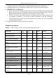
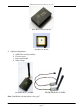
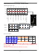
Defined Interface of the PANDA Flight Controller Module
Autopilot module interface pins:
Front row pins defined:
8
7
6
5
4
3
2
1
NO.
GND
VCC
TX1
RX1
Switch
input 1
Rudder
input
Throttle
input
Elevator
input
Ⅰ
GND
3.3V
TX2
RX2
GND
VCC
Aileron
input
Switch
input 2
Ⅱ
GND
5V
DL
DY
Ⅲ
NOTE: The pin “ Ⅱ-5,6,7,8”is for the GPS module, “Ⅱ-7”pin output +3.3V, “Ⅲ - 5,6,7,8”is
for the Current sensor , “Ⅲ - 7”pin is +5V output, please don’t supply to these pins, or will
burn the autopilot .
The output 1 is corresponding with the input of CH7 in the remote adapter.
Signal
+5V
GND
P6
P5
P4
P3
P2
P1
AD
P7
Parachute open
OUT
External voltage
acquisition
AIL OUT
ELE OUT
THR OUT
RUD OUT
Take photo OUT
Output 1
UART port
GPS port
CS port
Receiver signal input port