
Manual


Guilin Feiyu Electronic Technology Co., Ltd.
Guilin Feiyu Electronic Technology Co., Ltd http://www.feiyudz.cn service@feiyu-tech.com
Page 6
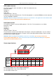
S3: connection ESC or throttle servo.
S4: connection rudder servo.
S5: connection aileron servo 2 (without setting mix control ,same signal as S1)
S6: not used
S7:When use Remote Adaptor, CH7 receiver output channel (detail please reference Remote Adaptor and
Data Radio introduction)
S8: When use Remote Adaptor, CH8 receiver output channel (detail please reference Remote Adaptor and
Data Radio introduction)
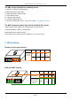
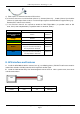
Plane connecting layout
1) Connection for traditional aircraft layout:
S1
S2
S3
S4
S5
Aileron
servo 1
Elevator
servo
ESC/throttle
servo
Rudder
servo
Aileron servo 2
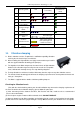
2) Connection for flying wing aircraft(with or without Rudder)
S1
S2
S3
S4
Differential
Servo 1
Differential
Servo 2
ESC/throttle
servo
Rudder
servo
3) Connection for V tail aircraft with Aileron
S1
S2
S3
S4
S5
Aileron
servo 1
Differential
Servo 1
ESC/throttle
servo
Differential
Servo 2
Aileron
servo 2
4) Connection for V tail aircraft without ailerons:
S1
S2
S3
S4
Differential
Servo 1
Differential
Servo 2
Throttle
servo
NULL
6. Power supply
● DOS input voltage is 4.0 ~ 6.0 V.
● DOS is powered via the RC receiver connection wires,the same power as RC receiver.
● If your plane is electric powered, the RC receiver power supply is normally from the ESC built-in Battery
Elimination Circuit (BEC). However, we highly recommend that a separate BEC with a +5V output.
● For Gas or Nitro powered planes, you will require a battery to power the RC receiver and DOS .
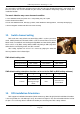
7. RC receiver connection
RC receiver and DOS connection wires is included in the DOS product. Attention: the wires is arranged by
the colors.