
Installation Instructions

5 WWW.FEIT.COM
Please contact 1-800-543-3348 for further assistance.
J-Box Installation
1
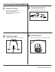
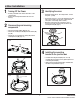
Turning Off the Power
2
Disconnecting and removing
components
3
Identifying the wires
□ Turn the power OFF at the switch and fusebox or the
circuit breaker.
□ Remove the existing trim installed in the recessed
housing.
□ Disconnect the E26 adapter (DD). (Fig. 4a)
□ Remove the mounting bracket (BB) from the xture (AA).
(Fig. 4b)
□ Remove the 4 in. mounting clip springs (CC) from the
mounting bracket (BB). (Fig. 4c)
□ Identify the wiring: (black - line voltage, white - neutral
and green - ground)
□ Use the wire nuts (JJ) to connect the stripped wires with
male connector (EE) to the two wires coming from the
J-box (black - line voltage, white - neutral).
□ Determine if the ground wire is inside the J-box. If
not, then secure the ground wire (FF) provided to the
mounting bracket (BB). (Fig. 5).
Fig.4a
Fig. 4b
Fig. 4c
Fig. 5
EE
BB
JJ
FF
CC
DD
BB
AA
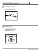
4
Installing the mounting
bracket to the junction box
□ Install the mounting bracket (BB) to the J-box by
inserting the two mounting screws (II) through the slots
in mounting bracket (BB).
□ Make sure the mounting bracket (BB) is installed with
the label facing downwards. (Fig. 6)
Fig. 6
II