LEDR4FP/830 USE AND CARE GUIDE DIMMABLE 4 IN. ROUND FLAT PANEL RECESSED DOWNLIGHT FEIT ELECTRIC COMPANY | PICO RIVERA, CA | (800) 543-3348 | FAX (562) 908-6360 | www.feit.
Table of Contents Table of Contents. . . . . . . . . . . . . . . . . . . . . . . . . . . . . . . . . . . . 2 Safety Information. . . . . . . . . . . . . . . . . . . . . . . . . . . . . . . . . . . 2 Warranty. . . . . . . . . . . . . . . . . . . . . . . . . . . . . . . . . . . . . . . . . . . 2 Pre-Installation. . . . . . . . . . . . . . . . . . . . . . . . . . . . . . .
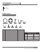
Pre-Installation TOOLS REQUIRED Phillips screwdriver HARDWARE INCLUDED NOTE: Hardware not shown to actual size. AA FF BB GG CC HH DD II EE JJ Part Description Quantity AA 5 in. fixture 1 BB Mounting bracket 1 CC 4 in. mounting clip spring 3 DD E26 adapter with male connector 1 DISTANCE CENTER BEAM (FOOT CANDLES) BEAM DIAMETER EE Stripped wires with male connector 1 3 FT. 23 8.6 FT. 5 FT. 8 14 FT. 8 FT. 3.2 23 FT. 15 FT. 0.9 43 FT. FF Ground wire 1 GG 4 in.
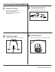
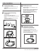
in. Recessed Can Installation 1 3 Turning Off the Power Connecting the terminals □□ Connect the two terminals together. (Fig. 2) □□ Turn the power OFF at the switch and fusebox or the circuit breaker. □□ Remove the existing trim installed in the recessed housing. Fig. 2 Connect the orange connectors 2 4 Installing the fixture Installing the adapter □□ Install the E26 adapter (DD) into the socket. (Fig. 1) □□ Gently push the fixture into the recessed housing. (Fig. 3) Fig. 1 Fig.
J-Box Installation 1 3 Turning Off the Power □□ Turn the power OFF at the switch and fusebox or the circuit breaker. □□ Remove the existing trim installed in the recessed housing. 2 Identifying the wires □□ Identify the wiring: (black - line voltage, white - neutral and green - ground) □□ Use the wire nuts (JJ) to connect the stripped wires with male connector (EE) to the two wires coming from the J-box (black - line voltage, white - neutral). □□ Determine if the ground wire is inside the J-box.
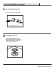
J-Box Installation (continued) 5 Connecting the terminals □□ Connect the two terminals together. (Fig. 7) Fig. 7 Connect the orange connectors 6 Installing the fixture □□ Secure the fixture (AA) to the mounting bracket (BB) by pressing the fixture into the mounting bracket until the clips on the fixture engage together. Make sure the fixture is firmly locked into place. (Fig. 8) Fig. 8 BB AA 6 WWW.FEIT.COM Retain this manual for future use.