
Installation Sheet

1
Installation Instructions for
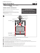
If necessary, screw the shorter end of the threaded nipple tightly onto the mounting plate.
Secure the mounting plate to the junction box.
Remove the frame and cover by unscrewing the frame screws.
Screw the lamps into the sockets. Refer to the label on the lamp socket for Max Wattage Information.
Insert the glass into the fixture frame, place the bottom cover on the bottom frame, and secure the bottom frame to the
fixture frame using the frame screws.
Connect the fixture to a suitable ground in accordance to local electrical codes.
Connect the white fixture wire to the neutral power line wire with a wire nut.
Connect the black fixture wire to the hot power line wire with a wire nut.
Place the fixture base and washer onto the threaded nipple, then secure them in place by screwing the hex nut onto the
nipple followed by the cap nut.
1
2
1A
3
4
1
1
6
7
8
5
9
MOUNTING PLATE
Angelo Flush Mount
1.0
FM530
FM530
FIXTURE BASE
CAP NUT
Ceiling
GP I :ENERAL RODUCT NFORMATION
These fixtures are intended to be installed utilizing NEC compliant junction
boxes.
This product is safety listed for damp locations.
Incandescent lamps may be dimmed with a standard incandescent dimmer.
LED lamps may be dimmed with a LED dimmer. Consult lamp manufacturer
for additional information.
This instruction shows a typical installation.
CAUTION RISK OF FIRE-
This product must be installed in accordance with the
applicable installation code by a person familiar with the
construction and operation of the product and the hazards
involved.
Use minimum 90°c supply conductors.
8
7
JUNCTION BOX
THREADED NIPPLE
HEX NUT & WASHER
9
FRAME SCREW
BOTTOM FRAME
BOTTOM COVER
4
4