FEDDERS LARGE SPLIT UNIT (R407C) SERVICE MANUAL ISSUED ON 1 APRIL,2003
SECTION A: SPECIFICATIONS SECTION B: PARTS LIST AND EXPLODED VIEWS SECTION C: INSTALLATION SECTION D: TROUBLE SHOOTING SECTION E: WIRING DIAGRAM SECTION F: TECHNICAL DATA
SECTION A: SPECIFICATIONS
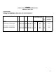
FEDDERS LARGE SPLIT (R407C) MODEL NUMBER Indoor unit Outdoor unit E1FE418N6D E1FC418N6G EHFE418N6D EHFC418N6G E1FE424N6D E1FC424N6G EHFE424N6D EHFC424N6G PERFORMANCE DATA Volts / Hz / Phase Cooling - BTU/h (kW) Heating - BTU/h (kW) Amps (Cooling / Heating) Watts (Cooling / Heating) EER (Cooling) Indoor Sound Level (dBA) Moisture Removel (Litres/h) Air Circulation - CMH (CFM) Interconnecting Tubing Maximum Tibing Length - m (ft) 220-240 / 50 / 1 220-240 / 50 / 1 220-240 / 50 / 1 220-240 / 50 / 1 17500
SECTION B: PARTS LIST AND EXPLODED VIEWS
FEDDERS LARGE SPLIT AIR CONDITIONER(R407C) SERVICE PARTS LIST SPECIFICATIONS : INDOOR UNIT DIMENSIONS : 1020(40.15")W x 195(7.68")D x 320(12.60")H OUTDOOR UNIT DIMENSIONS : 895(35.2")W x 331(13.0")D x 623(24.6")H AT STANDARD AHAM RATING CONDITIONS MODEL E1FE418N6D - E1FC418N6G EHFE418N6D - EHFC418N6G E1FE424N6D - E1FC424N6G EHFE424N6D - EHFC424N6G R E V BTU/h (kW) 17500 (5.13) 17500 (5.13) 18300 (5.36) MODE Volt / Hz COOL 220-240 / 50 COOL 220-240 / 50 HEAT 220-240 / 50 21500 (6.
FEDDERS LARGE SPLIT INDOOR EVAPORATOR UNIT (R407C) MODEL NUMBER E E E H 1 H F F F E E E 4 4 4 1 2 2 8 4 4 N N N 6 6 6 D D D Service Part # 1 2 3 Description -----CHASSIS ASSEMBLY----Lock Plate, Blower Wheel Left Lock Plate, Fan Motor, Right Lock Plate, Fan Motor, Left E 1 F E 4 1 8 N 6 D 36-08-00010-001 36-08-00020-001 36-08-00030-001 1 1 1 1 1 1 1 1 1 1 1 1 4 5 6 Motor, Discharge Cover Plate protect, Coil Water Tube Bracket 36-08-00050-001 36-08-00060-001 36-08-00070-001 1 1 1 1 1 1 1 1 1
FEDDERS LARGE SPLIT INDOOR EVAPORATOR UNIT (R407C) MODEL NUMBER E E E H 1 H F F F E E E 4 4 4 1 2 2 8 4 4 N N N 6 6 6 D D D Service Part # 24 Description -----CHASSIS ASSEMBLY(Cont')----Filter E 1 F E 4 1 8 N 6 D 35-16-00010-001 2 2 2 2 NI NI 3M Purifying Filter Charcoal Purifying Filter 35-03-01460-001 35-03-00260-001 1 1 1 1 1 1 1 1 25 26 27 Lens, Sensor Cover, Screw Label, LED Lens 36-08-00250-001 36-08-00260-001 36-08-00270-001 1 3 1 1 3 1 1 3 1 1 3 1 37-16-08540-001 1 1 1 1
FEDDERS LARGE SPLIT INDOOR EVAPORATOR UNIT (R407C) Item No. 41 Description -----ELECTRICAL ASSEMBLY(Cont')----Main P.C. Board (C/O) MODEL NUMBER E E E H 1 H F F F E E E 4 4 4 1 2 2 8 4 4 N N N 6 6 6 D D D Service Part # E 1 F E 4 1 8 N 6 D 35-16-04160-012 1 -- 1 -- 41 Main P.C.
FEDDERS LARGE SPLIT UNIT OUTDOOR CONDENSER UNIT (R407C) Item No.
MODEL NUMBER E E E H 1 H F F F C C C 4 4 4 1 2 2 8 4 4 N N N 6 6 6 G G G Service Part # 16 Description -----REFRIGERANT ASSEMBLY(Cont')----Capillary Tube, 0.
MODEL NUMBER E E E H 1 H F F F C C C 4 4 4 1 2 2 8 4 4 N N N 6 6 6 G G G Service Part # 34 Description -----PACKAGING PARTS----Carton,Neuter E 1 F C 4 1 8 N 6 G 35-24-00070-N01 1 1 1 1 35 36 EPS Pad, Top Left EPS Pad, Top Right 35-24-00030-001 35-24-00040-001 1 1 1 1 1 1 1 1 37 38 EPS Tie-bar EPS Side Post 35-08-02060-001 35-24-00020-001 1 2 1 2 1 2 1 2 39 40 EPS Side Pad EPS Bottom Pad 35-24-00050-001 35-24-00060-002 1 1 1 1 1 1 1 1 41 Carton Box Base 35-24-00080-001 1 1
SECTION C: INSTALLATION
® SPLIT TYPE AIR CONDITIONER INSTALLATION MANUAL For 18,000 - 24,000 Btu C1
CONTENTS SAFETY PRECAUTION ........................................................................... C3 PART LISTS ................................................................................................ C4 PREPARATION OF PIPING ................................................................... C5 Pipe Length, Elevation and refrigerant charge ....................... C5 Flaring of pipe ......................................................................................
SAFETY PRECAUTION • Please read the “Safety Precaution” carefully before installing the unit. • Pay special attention to signs of “WARNING” and “CAUTION”. The “Warning” section contains matters which, if not observed strictly, may cause death or serious injury. The “Caution” section contains matters which may result in serious consequences if not observed properly. Please follow all instructions strictly to help ensure your safety.
PART LISTS A number of small parts have been packed with the indoor unit. Please check the contents of the box with the list below.
PREPARATION OF PIPING Pipe Length, Elevation and refrigerant charge • Each outdoor unit comes with a refrigerant charge that is sufficient for use with interconnecting tubing up to 7.5 metres. • If the required interconnecting tube exceeds 5 metres, for each additional metre, add the amount of refrigerant according to the table as shown below. Liquid Pipe Additional Size Refrigerant 1/4” 21 g/m 3/8” 57 g/m Max. Piping Length per Indoor Unit Max.
PREPARATION OF PIPING Removing burrs • Remove burrs from the cut edges of the pipes. • Turn the pipe end down to avoid the metal powder entering the pipe. CAUTION : If burrs are not removed, they may cause a gas leakage when in operation. Flaring of pipe • Insert the flare nut or coupling nut over the tubing with the threaded end facing the end of the tubing. • Clamp the tube in the flaring block, adjust the tube so that it is slightly above the block (about 1/3 of the total height of the flare).
INDOOR UNIT INSTALLATION Locating the indoor unit • Do not install the unit near any heat Ceiling source, steam source or flammable gas At least 40mm source. At least 50mm • Locate the unit in a place where it will provide cool air throughout the room. • Make sure the minimum distances from Wall Wall At least 50mm the walls and obstructions are main- 2300-3000mm tained as shown on the right. Floor • Ensure that the unit’s airflow is not obstructed.
INDOOR UNIT INSTALLATION Removing The Decorative Front • Remove the Decorative Front by removing 3 screws. • Remove it by lifting it up and then out. Routing the drain hose and tubing • The following illustrate the different piping outlet option. Left Back Outlet Right Back Outlet If you are using the following outlet option, you must wire the indoor unit before attaching it to the wall bracket.
INDOOR UNIT INSTALLATION Sealing The Drain Hose And Tubing • Wrap the drain hose, tubing and electric wire together with polyethylene tape. • Wrap all exposed tubing with tape except tubing, which will rest inside the unit. Use caution Drain hose Polyethylene tape • Insert the tubing, hose and wire when bending Tubing Piping Tape through the wall tube with the drain hose in the lowest position.
INDOOR UNIT INSTALLATION Attaching The Unit To The Wall Bracket If you are using right, left or bottom piping outlet (see page 8) you must wire the unit before you attach it to the wall bracket. • Hook the unit to the hangers on top of the bracket first and then press the lower left and right side of the unit against the wall bracket until it is seated properly. • Ensure that the unit is level. • Ensure that the drain hose is in the Drain Hose proper position.
INDOOR UNIT INSTALLATION Connecting The Piping To The Indoor Unit • Align the center of the piping and then sufficiently tighten the Indoor unit tubing flare nut with fingers, tighten Flare nut the flare nut with torque wrench according to the table as shown below. Pipe Size Diameter Torque (N.m) 9.52mm (3/8”) 35.6 - 44.4 15.87mm (5/8”) 58.7 - 73.
OUTDOOR UNIT INSTALLATION Locating the outdoor unit • Locate the outdoor unit where the air flow around it is not obstructed. • Ensure that the base is level and does At least 60cm not exceed the maximum slope of 5 degrees. • Secure the unit to a base with anchor bolts to reduce vibrations and noise. At least 40cm At least 10cm • Place the unit with access space for servicing and maintenance. • Do not install the unit near a heat At least 60cm At least 60cm source, steam source and flammable gas.
OUTDOOR UNIT INSTALLATION Installing The Outdoor Unit • Attach the Base Leg Damper by Base Leg Damper sliding the slot into the base of the outdoor unit. • Attach the drain gasket and drain adapter to the base pan of the unit before you secure the unit. • Fasten the unit down, referred to the mounting dimensions as shown here. Drain Adapter 356mm 604mm Connecting The Pipe To The Outdoor Unit • Align the center of the piping and Liquid Line sufficiently tighten the flare nut with fingers.
OUTDOOR UNIT INSTALLATION Connecting The Wires To The Outdoor Unit • Remove the Service Cover from the unit. • Connect the wires to the terminals according to the wiring diagram shown in the wiring diagram section or at the back of the Service Cover. Screw Service Cover • Clamp the wire to the unit with the wire retainer. • Form a drip loop in the wire to prevent water from entering the unit along the cord.
VACUUMING THE PIPING & THE INDOOR UNIT Checking for gas leakage • Connect the Manifold gauge to the outdoor unit gas line port as shown Manifold gauge on the right. • Connect the charging cylinder to the Manifold gauge and open the valve of Charging Cylinder the Cylinder. 3-way valve • Open the low pressure valve of the Manifold gauge until the meter reads steady at about 150-200 psig. • Check for gas leakage especially around the tubing connectors with a gas-leak detector.
VACUUMING THE PIPING & THE INDOOR UNIT • Unscrew the cap on the 2-way and 3-way valve. • After all lines are installed and leak tested, set both the liquid and gas line valves to fully open position with the Allen Key for Using Allen Key to open fully for unit operation the unit operation, as shown. • Reinstall the cap and torque to the specified value under Torque Table on page 10.
TEST RUN & CHECK Switch On The Power Supply CAUTION : Ensure that all the piping and wiring are connected properly and securely, before turning the power On. • Turn the main switch of the unit to On. • Operate the Indoor unit at Cooling/Heating mode for fifteen minutes or more. • Measure the temperature of the intake and the discharge air, the temperature difference should be at least 9 oC.
NOTICE TO THE CONSUMER Checking The Unit • Check all the control functions. • Check all the indicator lights. • Check that the drain hose is draining properly. • Ensure all the units are fastened properly and free from vibrations. Upon completion of installing and checking the unit: • Supply the consumer with the Operating Manual. • Demonstrate the functions of the remote control. • Demonstrate how to remove and clean the air filters. • Explain the 3 minute delay function.
SECTION D: TROUBLE SHOOTING
D1
SYMPTOM DIAGNOSIS REMEDY Both fan & compressor not running. Fuse open or breaker tripped. Poor power plug connection. Power failure. Control circuit malfuction. Inspect and repair. Inspect. Inspect. Replace parts. Compressor does not run. Replace compressor. Replace compressor. Replace part. Replace part. Replace part. Check supply wiring. Restart in 10 minutes. Inspect Control Circuit. Replace part. Replace part. Replace part. Replace part. Inspect. Leak repair and replenish gas.
SECTION E: WIRING DIAGRAM
E1
E2
E3
E4
SECTION F: TECHNICAL DATA
REMOTE CONTROL AND PC BOARD FUNCTIONAL SPECIFICATIONS LARGE SPLIT UNIT (18 / 24K) The electronic air-con control system consists of : I.
II. Hand-held Transmitter Operating Voltage : 3.0 Vdc.
h) CLOCK button Starts and stops the setting of time of the day. Deactivates timer function. The accuracy of the time setting must be + / - 15 second per day. i) SLEEP button Activates / deactivates sleep function j) START button Activate / deactivate ON timer k) STOP button Activates / deactivates OFF timer l) HR. button Adjusts the hour setting of the time of the day if the CLOCK button has been pressed prior to this step.
1.1. Operation / Filter Reset Button. Operation By pushing this button, one of the following two air-con operations are selected. a) AUTOMATIC operation Selecting this operation is equivalent to selecting Auto mode, auto fan speed control and auto vane function in manual operation. The set temperature is internally fixed at 22°C and cannot be changed. This operation is useful when the hand held transmitter is lost or faulty. b) OFF operation The air-con will be switched off.
c) Filter dirty/System Fault (red) LED Lights up after 500 hours of operation, to indicate that the filter requires cleansing. The Operation/Filter reset switch should be pressed by the user to switch this LED indication off after cleansing and replacing the filter. When Indoor air thermistor (TH1) fault. It blinks at approximately 30 times per minute, only indoor fan is operating and reset by turning off main power supply. When Indoor Coil thermistor (TH2) fault.
3. 3-min. compressor switch on delay The compressor is not switched on again immediately after being switched off. The air-con controller waits for 3 minutes before turning it on again to protect it. This protective measure applies throughout the operation of the air-con except on power-up. 4. 60-second 4-way valve delay (applicable on Heat Pump Unit only) This refers to the 60-second delay after turning off compressor before the 4-way valve is switched over from off to on or vice-versa.
V. Modes of Operation 1. Cool Mode The air-con controller lowers the room temperature in this mode. In cool mode, the indoor fan is always turned on, allowing it to run at the set speed. To stop the cool mode cycle, the compressor, outdoor fan are turned off, the 4-way valve which serves no function in this mode is still kept at off. The indoor fan is however allowed to continue running at set speed. The controller monitors room temperature and compares it against set/desired temperature.
If the room temperature >=31°C, compressor off, outdoor fan off and 4-way valve remains on, indoor fan runs according to following table: ID Room Temp., Tr Tr<=31°C ID Fan SET * Maintain current state 31°C=32°C LOW The heating cycle starts and stops according to the result of set temperature - room temperature comparison: < Set pt-1°C = Set pt-1°C = Set pt. ID Room Temp.
VI. Temperature Control and Measurement 1. Temperature Measurement Accuracy The temperature measurement range of the air-con controller is from -10ºC to 60ºC.
When the indoor fan control is set to Auto, the fan speed is automatically selected according to the mode of operation, set temperature and room temperature. In cool mode, choosing Auto Fan will result in the following automatic fan speed selection: Room Temperature < Set pt-3°C = Set pt-3°C = Set pt.
VIII. Vane Function 1. Vane Position HOME The vane will be at this position whenever the air-con is off. Its exact angle is 115° counter-clockwise from position 3. POSITION 1 The vane plane is positioned 70° counter-clockwise from position 3. cool, dry and fan modes default vane position. POSITION 2 The vane plane is 50° counter-clockwise from position 3. POSITION 3 The vane plane is vertical (Heat mode default vane position). NB.
IX. Sleep Function Sleep function is only selectable in manual operation, but it is not available in dry and fan modes. When this function is selected, the Indoor Fan immediately runs at low speed, all timer functions will be overridden and disabled at the same time. In cool or auto-cool mode, One hour after Sleep function is selected, the temperature set point will be raised by 1ºC. Two hours later, the set temperature will be raised by another 1ºC.
X. Timer Function The start timer will switch the air conditioner ON at the start time set in the hand-held transmitter, while the stop timer will switch the air-con OFF at the specified stop time. Both timers can be activated together to perform "ON-OFF-ON" or "OFF-ON-OFF" operation. The setting of the timers is done using the HR. and MIN. buttons of the hand-held transmitter in steps of 10 minutes. The LCD panel on the hand-held transmitter will show the start and/or stop times of timer operation.
XI. Device Protection Measures 1. 3-minutes compressor switch on delay The compressor is not switched on again for 3-minutes every time after it is switched off to protect it. This restriction applies throughout the operation of the Air-con except on powerup. 2.
For example, if the temperature set point is 20°C when cool mode is entered at a room temperature of 21°C, the controller will start the cool mode cycle to cool the room. The cycle still continues when the room temperature later lowers to 20°C. It finally stops when the room temperature lowers further to 19°C. If the room temperature subsequently rises to 20°C again, the cool mode cycle will still not start. The cool mode cycle will only start when the room temperature rises further to 21°C.
When the indoor coil temperature reaches 10ºC or higher for 2 minutes de-icing will be terminated and normal cool mode operation resumes. However, if the coil temperature is still below 10ºC after 10 minutes, de-icing operation will still be terminated to resume normal cool mode operation. 40 minutes after the completion of one de-icing cycle, another detection of the indoor coil temperature is made. If the indoor coil temperature detected is less than 2ºC, then another deicing cycle is executed.
6. Defrosting in HEAT mode (applicable on Heat Pump Unit only) a) Defrost starting conditions When all conditions of i) ~ iii) are satisfied, defrosting operation starts. i) The indoor coil thermistor read ≤42°C ii) The outdoor coil thermistor reads -4°C or below. iii) The difference between the Indoor-coil Thermistor and Indoor air thermistor ≤ 22°C. Further information on defrost interval is described in (3).
7. Outdoor Coil De-icing in Heat Mode (applicable on Heat Pump Unit only) The air-con controller heats up the outdoor coil to melt the ice formed at outdoor coil. To achieve this, the compressor must be turned on, while the 4-way valve must be turned off. During this period, the indoor fan must be switched off with exception condition as stated in Note 1. otherwise it will fill the room with cool air and cause discomfort to the users. Defrost thermistor below 40 °C Below –4 °C Compressor ON OFF 60 sec.
XII. Thermistor fault indication The electronic controller flashes the filter LED when a thermistor fault is detected. The filter LED blinking according to the time specified until the thermistor fault is rectified. 1. Heat Overload Protection Algorithm Large-Split Heatpump Comp. ON OD Fan ON ID Fan Set Comp. ON OD Fan ON ID Fan Set Comp. OFF OD Fan OFF ID Fan High Comp. ON OD Fan OFF ID Fan High Comp. ON OD Fan OFF ID Fan High Comp. ON OD Fan ON ID Fan Set Comp. ON OD Fan OFF ID Fan High Comp.
XIII. Self Test Main PCB Self-test To initiate the self-test sequence, execute the following: a) Turn on the ac. supply to the air-con. b) Press and hold the Operation / Filter reset button for 6 seconds after which you can hear 2 beep sound to indicate activation of self-test sequence. (Note : When press and hold for 3 seconds, a single beep will be heard. Keep on holding for another 3 seconds to achieve the total 6 seconds requirement to activate the self-test sequence.) Observe the following events.
F21
F22
F23
F24
F25
F26
F27
F28