
Manual


Chapter 4: System Setup and Wiring
Page 4-52
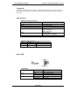
DeviceNet Signal I/O Map
From Fusion to PLC : 8 Words (16 Bytes – 128 Bits)
Data
Bit
No.
Signal Description
Comment
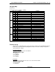
0
0 1 End
1 2 Accept
2 3 Reject
3 4
4 5
5 6 Job Cycle Accepted Future
6 7 Job Done Status Aborted Future
7 8
0
8 9
9 10
10 11 Time 1 Reject
11 12 Time 2 Reject
12 13 Work Select Bit 0 / Job Bit 0 (echo) Job Function is Future
13 14 Work Select Bit 1 / Job Bit 1 (echo) Job Function is Future
14 15 Work Select Bit 2 / Job Bit 2 (echo) Job Function is Future
15 16 Work Select Bit 3 / Job Bit 3 (echo) Job Function is Future
0
16 17 Reject
17 18 Accept
18 19 Abnormal
19 20 Ready
20 21 Busy
21 22 Torque High Reject
22 23 Torque Low Reject
23 24 Bypass
0
24 25 Angle High Reject
25 26 Angle Low Reject
26 27 Rate1 High Reject
27 28 Rate1 Low Reject
28 29 Rate2 High Reject
29 30 Rate2 Low Reject
30 31 Rate3 High Reject
31 32 Rate3 Low Reject
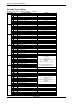
1
0 33 Torque Integer bit 0
Outputs Fastening Torque using bi-
nary integer
0 - 999 max.
(number LEFT of decimal only)
Example:
bit 2, 4, 7 Logical "1" = 148
Total Torque including Torque de-
cimal (word3) = 148.38
1 34 Torque Integer bit 1
2 35 Torque Integer bit 2
3 36 Torque Integer bit 3
4 37 Torque Integer bit 4
5 38 Torque Integer bit 5
6 39 Torque Integer bit 6
7 40 Torque Integer bit 7
1
8 41 Torque Integer bit 8
9 42 Torque Integer bit 9
10 43
11 44
12 45
13 46
14 47
15 48
1
16 49 Torque Decimal bit 0
Outputs Fastening Torque Decimal
value using binary integer
0 - 99 max.
(number RIGHT of decimal only)
Example:
bit 1, 2, 5 Logical "1" = 38
17 50 Torque Decimal bit 1
18 51 Torque Decimal bit 2
19 52 Torque Decimal bit 3
20 53 Torque Decimal bit 4
21 54 Torque Decimal bit 5
22 55 Torque Decimal bit 6
23 56
1
24 57
25 58
26 59
27 60
28 61
29 62
30 63
31 64