
Manual


Chapter 4: System Setup and Wiring
Page 4-48
4.15.3 Fieldbus Interfaces – DeviceNet
®
DeviceNet
®
Interface
The DeviceNet communication interface allows slave connection to an industrial DeviceNet net-
work. DeviceNet allows industrial devices to be controlled over an open network architecture
enabling device connection at various locations in the field. This “fieldbus” technology reduces
hard wiring/cabling & provides ease of installation. It uses a broadcast-oriented protocol -the CAN
(Controller Area Network)- that can interface to many devices such as limit switches, sensors, di-
rectional valves, motor starters, bar code readers, process sensors, frequency drives, etc. The
network can have up to 64 nodes.
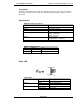
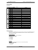
Maximum I/O data is 512 input bytes & 512 output bytes. FEC Inputs/Outputs are shown in the
following I/O signal map layout.
Note: The DeviceNet interface is implemented according to the ODVA specification for a commu-
nications adapter (profile no.12). It is acting as a “group two only server” on the DeviceNet net-
work.
FEC integrates the DeviceNet board manufactured by HMS Fieldbus Systems AB into the Multi-
Unit modular I/O board. For further technical information on the DeviceNet interface go to the
HMS website. (www.hms.se)
Further DeviceNet information can be found through the Open DeviceNet Vendors Association
(ODVA). (www.ODVA.org)
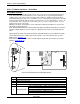
Interface Board with DeviceNet Daughter Board
Item
Description
1 Application Connector
2 DeviceNet Connector
3 Configuration Switches
4 Status LEDs (4)
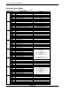
5 Watchdog LED
Red - (flashing @ 2Hz) - ASIC and FLASH ROM check fault.
Green (flashing @ 2Hz) - module not initialized.
Green (flashing @ 1Hz) - module initialized and running OK.
Red (flashing @ 1Hz) - RAM check fault.
Red (flashing @ 4Hz) - DPRAM check fault.
2
1
3
4
5