
Manual


Chapter 4: System Setup and Wiring
Page 4-46
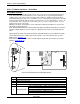
Dip Switch Setting
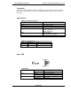
Address setting (DIP switch)
SW
-
3
(LSB)
SW
-
4
SW
-
5
SW
-
6
SW
-
7
SW
-
8
MAC ID
OFF OFF OFF OFF OFF OFF Address 0*
ON OFF OFF OFF OFF OFF Address 1
OFF ON OFF OFF OFF OFF Address 2
ON ON OFF OFF OFF OFF Address 3
.
.
.
.
.
.
.
ON OFF OFF ON ON ON Address 57
OFF ON OFF ON ON ON Address 58
ON ON OFF ON ON ON Address 59
This switch must be set before power is on, and cannot be changed during operation.
*Address should be set to “0” if this is the only device on the network.
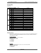
Baud rate setting (DIP switch)
SW
-
1
SW
-
2
Baud rate
OFF OFF 57.6K
ON OFF 115K
OFF ON 230K
ON ON Reserved
Baud rate must match the settings of the Remote I/O scanner.
This switch must be set before power is on, and cannot be changed during operation.
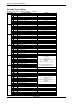
I/O Signal Map
From Fusion to PLC – (4 Bytes – 32 Bits)
Octal
Bit
Signal Description
Comment
I:00
0 0 End
1 1 Accept
2 2 Reject
3 3
4 4
5 5 Job Cycle Accepted Future
6 6 Job Done Status Aborted Future
7 7
I:00
10 8
11 9
12 10 Time 1 Reject
13 11 Time 2 Reject
14 12 Work Select Bit 0 / Job Bit 0 (echo) Job Function is Future
15 13 Work Select Bit 1 / Job Bit 1 (echo) Job Function is Future
16 14 Work Select Bit 2 / Job Bit 2 (echo) Job Function is Future
17 15 Work Select Bit 3 / Job Bit 3 (echo) Job Function is Future
I:01
0 0 Reject
1 1 Accept
2 2 Abnormal
3 3 Ready
4 4 Busy
5 5 Torque High Reject
6 6 Torque Low Reject
7 7 Bypass
I:01
10 8 Angle High Reject
11 9 Angle Low Reject
12 10 Rate1 High Reject
13 11 Rate1 Low Reject
14 12 Rate2 High Reject
15 13 Rate2 Low Reject
16 14 Rate3 High Reject
17 15 Rate3 Low Reject