
Manual


Chapter 4: System Setup and Wiring
Page 4-42
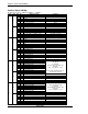
Profibus Signal I/O Map
From Fusion to PLC : 8 Words (16 Bytes – 128 Bits)
Word
Byte
Bit
No.
Signal Description
Comment
0
0
0 1 End
1 2 Accept
2 3 Reject
3 4
4 5
5 6 Job Cycle Accepted Future
6 7 Job Done Status Aborted Future
7 8
1
0 9
1 10
2 11 Time 1 Reject
3 12 Time 2 Reject
4 13 Work Select Bit 0 / Job Bit 0 (echo) Job Function is Future
5 14 Work Select Bit 1 / Job Bit 1 (echo) Job Function is Future
6 15 Work Select Bit 2 / Job Bit 2 (echo) Job Function is Future
7 16 Work Select Bit 3 / Job Bit 3 (echo) Job Function is Future
1
2
0 17 Reject
1 18 Accept
2 19 Abnormal
3 20 Ready
4 21 Busy
5 22 Torque High Reject
6 23 Torque Low Reject
7 24 Bypass
3
0 25 Angle High Reject
1 26 Angle Low Reject
2 27 Rate1 High Reject
3 28 Rate1 Low Reject
4 29 Rate2 High Reject
5 30 Rate2 Low Reject
6 31 Rate3 High Reject
7 32 Rate3 Low Reject
2
4
0 33 Torque Integer bit 0
Outputs Fastening Torque using bi-
nary integer
0 - 999 max.
(number LEFT of decimal only)
Example:
bit 2, 4, 7 Logical "1" = 148
Total Torque including Torque de-
cimal (word3) = 148.38
1 34 Torque Integer bit 1
2 35 Torque Integer bit 2
3 36 Torque Integer bit 3
4 37 Torque Integer bit 4
5 38 Torque Integer bit 5
6 39 Torque Integer bit 6
7 40 Torque Integer bit 7
5
0 41 Torque Integer bit 8
1 42 Torque Integer bit 9
2 43
3 44
4 45
5 46
6 47
7 48
3
6
0 49 Torque Decimal bit 0
Outputs Fastening Torque Decimal
value using binary integer
0 - 99 max.
(number RIGHT of decimal only)
Example:
bit 1, 2, 5 Logical "1" = 38
1 50 Torque Decimal bit 1
2 51 Torque Decimal bit 2
3 52 Torque Decimal bit 3
4 53 Torque Decimal bit 4
5 54 Torque Decimal bit 5
6 55 Torque Decimal bit 6
7 56
7
0 57
1 58
2 59
3 60
4 61
5 62
6 63
7 64