
Manual


FEC FUSION Operations Manual Chapter 4: System Setup and Wiring (Rev. 2.1)
Page 4-13
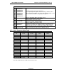
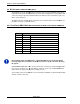
OUTPUT SIGNALS
A14
B14
A13
B13
A12
B12
A11
B11
BANK DATA 7
BANK DATA 6
BANK DATA 5
BANK DATA 4
BANK DATA 3
BANK DATA 2
BANK DATA 1
BANK DATA 0
Bank Data Output Signals (Normally Open)
These output signals designate various fastening conditions and re-
sults as determined by Bank Select 0 & 1 (Pins A4 & B4) inputs. Refer
to 4.7.3 Bank Select Table for output data descriptions.
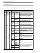
B15
B16
Relay Contact “A”
Future Programmable D
ry Contact Relay output
Rating : 0.3A @125VAC or 1A @ 30VDC
A15
A16
Relay Contact
“CYCLE END”
Cycle End
Dry Contact Relay output
Output when Reverse Mode is active and Operator activates start trig-
ger (used as operator “Auxiliary Output”)
B17
B18
Relay Contact
“WORK OK”
Batch Accept Dry Contact Relay output
Output after the number of accepts programmed in the Work Count
parameter is met. (D-No 74) (Rating as above) Output can be pro-
grammed as either “Pulse” or “State” type using the AFC software.
A17
A18
Relay Contact
“Pulsed Accept”
Accept Pulse (300
–
500 msec) Dry Contact Relay output
–
used to
replace a QL click style torque wrench. (Rating as above)
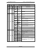
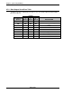
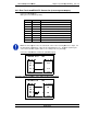
4.7.2 Work / Parameter Select Table
PARAMETER
NO.
WORK SELECT 3
PIN A6
WORK SELECT 2
PIN B6
WORK SELECT 1
PIN A5
WORK SELECT 0
PIN B5
1 OFF OFF OFF OFF
2 OFF OFF OFF ON
3 OFF OFF ON OFF
4 OFF OFF ON ON
5 OFF ON OFF OFF
6 OFF ON OFF ON
7 OFF ON ON OFF
8 OFF ON ON ON
9 ON OFF OFF OFF
10 ON OFF OFF ON
11 ON OFF ON OFF
12 ON OFF ON ON
13 ON ON OFF OFF
14 ON ON OFF ON
15 ON ON ON OFF
16 ON ON ON ON
OFF = Disabled
ON =Enabled
Note: TB1 terminal must be enabled. (See Section 7.2.4)