
Manual


FEC FUSION Operations Manual
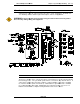
4.7 Wiring PLC I/O
All interface devices must accommodate active true low logic for correct operation with
FUSION
CONTROLLER
provided for isolated connection to an external controller.
available.
Outputs are rated at 12~24 VDC, 200mA. When activated, open collector sink
outputs (normally high) pull the input device signal low (0 VD
and activated when pulled low (0 VDC).
Once wired, the
TB1
ing the c
aptive screws located at the top and bottom of the
over to a new controller without disconnecting the terminal wires.
CAUTION:
The PLC I/O wiring must be routed a minimum of 300 mm away from any transient high vo
tage sources. Cable length must not exceed 50 feet.
DO NOT connect a positive DC
*
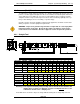
Output signals shown on terminals A11
SELECT inputs are used, these outputs WILL CHANGE DEFINITION
Select output table
FEC FUSION Operations Manual
Chapter 4: System Setup and Wiring (Rev. 2.1)
Page 4-11
All interface devices must accommodate active true low logic for correct operation with
CONTROLLER
Unit DC inputs and outputs (I/O).
Four output relay
provided for isolated connection to an external controller.
Optional F
ieldbus interface
Outputs are rated at 12~24 VDC, 200mA. When activated, open collector sink
outputs (normally high) pull the input device signal low (0 VD
C). Inputs are (normally high)
and activated when pulled low (0 VDC).
TB1
t
erminal block can be quick disconnected from the Controller by
aptive screws located at the top and bottom of the
terminal strip, for quick
over to a new controller without disconnecting the terminal wires.
The PLC I/O wiring must be routed a minimum of 300 mm away from any transient high vo
tage sources. Cable length must not exceed 50 feet.
DO NOT connect a positive DC
voltage source to the output common.
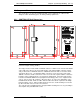
FIG. 4-7-1 Controller Unit PLC Connector
Output signals shown on terminals A11
–
B14 are for BANK 1 signals only. If BANK
SELECT inputs are used, these outputs WILL CHANGE DEFINITION
according to the Bank
and the selection of BANK SELECT INPUTS.
Chapter 4: System Setup and Wiring (Rev. 2.1)
All interface devices must accommodate active true low logic for correct operation with
the
Four output relay
contacts are
ieldbus interface
s are
Outputs are rated at 12~24 VDC, 200mA. When activated, open collector sink
C). Inputs are (normally high)
erminal block can be quick disconnected from the Controller by
loosen-
terminal strip, for quick
change-
The PLC I/O wiring must be routed a minimum of 300 mm away from any transient high vo
l-
B14 are for BANK 1 signals only. If BANK
according to the Bank