
Manual


Chapter 3: System Description
Page 3-4
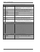
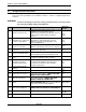
FRONT PANEL DISPLAY FEATURES
ITEM
ITEM AS MARKED ON UNIT
DESCRIPTION
1 ACCEPT
(Green) Lights to indicate that the spindle has completed an
acceptable fastening cycle. Flashes for an individual accept
during a Batch Count.
2 WORK ACCEPT
(Green) Lights to indicate that the spindle has completed an
acceptable group of fastenings. (Reached Batch Count No.)
3 REJECT
(Red). Indicates the spindle performed a rejected fastening, out
of the operation limits. Flashes indicating a rate reject.
4 TORQUE
(Yellow). Indicates the “Data Display LED” is displaying Torque
fastening Data.
5 ANGLE
(Yellow). Indicates the “Data Display LED” is displaying Angle
fastening Data.
6 LED Display
Four digit display which function is dependent upon the D-NO
selected.
“
” is displayed here during an “Abnormal” condition.
7 WORK
Displays two-digit parameter number and, as required, will
override parameter output to display an Abnormal code.
8 COUNT/D-NO.
Display number that indicates which data in the "DATA" display
field is being displayed and as required, will display an Abnormal
Sub-code. Displays Fastening Count during Batch Count
function.
FRONT PANEL CONTROL FEATURES
9 CAL Manual calibration (CAL) check pushbutton
10 RESET Manual zero check and system reset pushbutton.
11 UP - Arrow Data change increase pushbutton.
12 DOWN - Arrow Data change decrease pushbutton.
13 MODE Display mode selection pushbutton.
14 SET Data change confirmation set pushbutton.
15 WORK RIGHT - Arrow Parameter selection increase pushbutton.
16 WORK LEFT - Arrow Parameter selection decrease pushbutton.
17 POWER 0 / 1 0-Off / 1-On controller power switch
FRONT PANEL CONNECTOR FEATURES
18 T/A MON.
Optional DB9 connector for Torque / Angle monitor.
Analog outputs for use with external analysis equipment.
19 PC
RS232 communications port for interfacing with the AFC user
console software.