
Manual


Chapter 9: Troubleshooting
Page 9-2
9.1 Abnormal Conditions.
When an abnormal condition is detected by the system, the affected spindle stops, and lights
“Abn” in the [DATA] display. For ease of troubleshooting the nature of the abnormal, the sys-
tem provides an abnormal code in the [PARM] display and an abnormal sub-code in the
[COUNT/D-NO] display.
Note: ABNORMALS are not to be confused with fastening REJECTS. Abnormal’s signify a
failure of a system process or self check during the fastening cycle.
• Abnormal code display.
When an Abnormal condition occurs, the display mode will automatically change to the
STATUS mode. (If the display is not in the STATUS mode, depress the MODE button until a
blinking “A” appears in the [WORK] display area) A code number appears at the right side of
the blinking character. This code refers to some specific type of failure detailed in the tables
shown in the following sections.
• Abnormal Sub-code display.
The number shown at the most right position in the [COUNT/D-NO] display area is a sub-
code that can be used in conjunction with the Abnormal failure code to further narrow down
the cause of the fault. See the following sections.
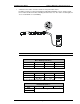
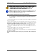
Example of Abnormal Code 9 Sub-Code 0
Abnormal Code Table
ABNORMAL
CODE
DESCRIPTION
1 Torque Transducer Error.
2 Over Torque Error.
3 Tool EEPROM error.
4 System Memory Error.
5 Servo Amplifier Reply Error.
6 Servo Type Mismatch Error.
7 NOT USED
8 Servo Amplifier Error.
9 Parameter Error.
Abnormal sub-codes and specific actions for troubleshooting are detailed in the following
section.
WARNING:DO NOT CONNECT OR DISCONNECT CABLES OR OTHER SYSTEM
COMPONENTS WITH POWER APPLIED.