
Manual


Chapter 7: System Operations
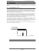
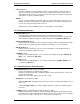
Abnormal “A9” Display
FIG. 7-1-
3 Fastening Displays
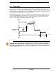
7.1.4 Fastening Prese
tting / Result Display Controls
• MODE button
Used to change modes while in the Run state. (Refer to 7.2)
Used to move the cursor while in the Bypass (program) state. (Refer to 7.3)
• SET button
Used to enter the
data in edit mode, and to confirm data setting change.
• MODE and SET
buttons Depressed simultaneously
Switches unit between Run state and Bypass (program) State.
• [↑
↑↑
↑] and [↓
↓↓
↓] Cursor key (V
ertical arrows).
Used to scroll through available data preset items. (D
Used to change display data values. (DATA)
Used as YES/NO acknowledge for Tool type and Torque unit changes
the Parameter copy function.
(Fig 7
• [
] and [
]
Cursor key (Horizontal arrows).
Used to scroll through available (16) parameter numbers.
Selection of [WORK]
# is for actual Fastening Operational Selection
form while in Run State.
Arrows are u
sed to select the appropriate Parameter for preset verification and changing
while in the Bypass State.
(Alternative WORK input
while in
(See Section 7.2.5, item 5 for more information on set
(TB1) method for Work Selection)
Page 7-4
Parameter No. 1 Cal “E” Fault
3 Fastening Displays
tting / Result Display Controls
Used to change modes while in the Run state. (Refer to 7.2)
Used to move the cursor while in the Bypass (program) state. (Refer to 7.3)
data in edit mode, and to confirm data setting change.
buttons Depressed simultaneously
Switches unit between Run state and Bypass (program) State.
ertical arrows).
Used to scroll through available data preset items. (D
-NO)
Used to change display data values. (DATA)
Used as YES/NO acknowledge for Tool type and Torque unit changes
and for confirmation of
(Fig 7
-3-6)
Cursor key (Horizontal arrows).
Used to scroll through available (16) parameter numbers.
[WORK]
# is for actual Fastening Operational Selection
, that the Tool will pe
sed to select the appropriate Parameter for preset verification and changing
while in
Run State available though use of PLC inputs.)
(See Section 7.2.5, item 5 for more information on set
-up select
ion using the Terminal I/O
(TB1) method for Work Selection)
and for confirmation of
, that the Tool will pe
r-
sed to select the appropriate Parameter for preset verification and changing
ion using the Terminal I/O