
Manual


Chapter 6: Fastening Instructions
6.2.4 Point-to-
Point Torque Rate Monitoring
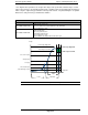
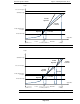
The Fusion
System is capable of performing 3 torque rate calculations. The Point
rate method performs the calculation based upon completing a step of the process, and then calcula
ing the rate f
or the full duration of that step. The chart below identifies the different areas that torque
rate can be calculated. Each Torque Rate is calculated by dividing the change in torque during the
specific period by the change in angle.
Example: 25Nm /
100deg. = 0.25 Nm/Deg. (rate)
NOTE: Setting any of
the Torque Rate
END TORQUE
will eliminate the torque rate
Torque Rate Calculation Areas (
(CROSSOVER TORQUE
set abo
Refer to Fig. 6-2-4a
STAGE
1ST TORQUE RATE
2ND TORQUE RATE
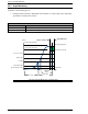
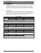
Torque Rate Calculation Areas (Typical for 3 step, however can be used on 1 or 2
Refer to Fig. 6-2-4b
STAGE
1ST TORQUE RATE
2ND TORQUE RATE
3RD TORQUE RATE
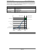
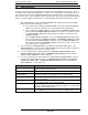
In the case that Torque
Rate Stop Points are not
to 2
ND
RATE START TORQUE and then to CROSSOVER TORQUE, the rate calculation will
be performed at the next successive available stop point prior to
STAGE
1ST TORQUE RATE
2ND TORQUE RATE
3RD TORQUE RATE
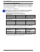
For all control operations, the High and Low Torque Rate limits are set by determinin
acceptable limits from a study of known good and bad assemblies.
Page 6-18
Point Torque Rate Monitoring
System is capable of performing 3 torque rate calculations. The Point
-to-
Point torque
rate method performs the calculation based upon completing a step of the process, and then calcula
or the full duration of that step. The chart below identifies the different areas that torque
rate can be calculated. Each Torque Rate is calculated by dividing the change in torque during the
100deg. = 0.25 Nm/Deg. (rate)
the Torque Rate
START POINTS above the FASTENING
will eliminate the torque rate
calculation for that stage.
Torque Rate Calculation Areas (
Typical for 1 or 2 step)
set abo
ve FASTENING END TORQUE)
START POINT
STOP POINT
THRESHOLD TORQUE
1ST TORQUE
2ND RATE START TORQUE
FASTENING END
Torque Rate Calculation Areas (Typical for 3 step, however can be used on 1 or 2
START POINT
STOP POINT
THRESHOLD TORQUE
1ST TORQUE
2ND RATE START TORQUE
CROSSOVER TORQUE
CROSSOVER TORQUE
FASTENING END
Rate Stop Points are not
set incrementally larger from THRESHOLD
RATE START TORQUE and then to CROSSOVER TORQUE, the rate calculation will
be performed at the next successive available stop point prior to
fastening end.
START POINT
AVAILABLE
STOP POINT
THRESHOLD
1ST TORQUE
CROSSOVER TORQUE
FASTENING END
2ND RATE START
CROSSOVER TORQUE
FASTENING END
CROSSOVER TORQUE
FASTENING END
For all control operations, the High and Low Torque Rate limits are set by determinin
acceptable limits from a study of known good and bad assemblies.
Point torque
rate method performs the calculation based upon completing a step of the process, and then calcula
t-
or the full duration of that step. The chart below identifies the different areas that torque
rate can be calculated. Each Torque Rate is calculated by dividing the change in torque during the
START POINTS above the FASTENING
FASTENING END
Torque Rate Calculation Areas (Typical for 3 step, however can be used on 1 or 2
step)
CROSSOVER TORQUE
FASTENING END
set incrementally larger from THRESHOLD
RATE START TORQUE and then to CROSSOVER TORQUE, the rate calculation will
STOP POINT
S
CROSSOVER TORQUE
FASTENING END
CROSSOVER TORQUE
FASTENING END
FASTENING END
For all control operations, the High and Low Torque Rate limits are set by determinin
g the