FUSIONE-HS-2
WARNING All applicable national and local codes must be followed when installing and operating the equipment detailed in this manual. FAILURE TO ABIDE BY THESE CODES AND THE SPECIFICATIONS DESCRIBED IN THIS MANUAL CAN RESULT IN SERIOUS INJURY TO PERSONNEL AND/OR DAMAGE TO THE EQUIPMENT! Any questions regarding the contents of this document or any related matter should be directed to FEC INC. at (586) 781-2100, faxed to (586) 781-0044 or emailed to: support@fec-usa.com.
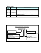
Revision History Revision date Manual No. 2005/July First Edition 2007/August FUSIONE-HS-2 2008 / June FUSIONE-HS-2 2008 / July FUSIONE-HS-2 Content of Revision Original Operation Manual Revision 2 - Updated format & added relevant information MINOR Revision – Chapter 2 – Page 2-4 (Chapter Rev. 2.1 now) Updated Power Consumption (Running & Idle) MINOR Revision – Chapter 4 – Page 4-48 – 4-53 (Chapter Rev.2.
Introduction Thank you for purchasing our Electric Servo Nutrunner – FUSION System. This instruction manual describes the procedures for installation, wiring, and handling, and actions to be taken in case of any failure. This instruction manual shall be delivered to the end user who operates the equipment. Read all instructions before use, and always keep this instruction manual with the equipment. Items not described in this instruction manual shall be considered “unavailable”.
Introduction Warranty Warranty Period The standard warranty period is one year from the date of purchase or one year from delivery to the designated End User (not to exceed 18 Months). Actual terms are order specific. Provision of warranty If your product proves to be defective, although it has been used properly in accordance with this instruction manual, during the period of warranty, this product will be repaired free of charge.
Safety Precautions Read ead all instructions before operating the equipment in order to use this equipment safely and correctly. Prior to use, read this instruction manual carefully and fully understand the equipequi ments functions, safety precautions and instructions.. Safety precautions in this manual are marked with two symbols [Warning] and [Caution].
Safety Precautions Warning Do not remove the motor motors and gear cases of tools while power is applied.. applied. The tool output spindle may rotate and cause injury. Do not repair, disassemble, or modify the equipment individual components of the system.. system. Failure to observe this instruction may cause injury, electric shock, fire, and malfunction. Never operate the eq equipment where it is exposed to water, near a corrosive atmosphere or flammable gases gases.
Safety Precautions Transportation / Storage Caution Transport the equipment properly according to its weight. Failure to observe this instruction may cause injury and malfunction. The conditions when transporting the equipment by ship is as below. Ambient temperature: --5°C +55°C (Avoid freezing) Ambient humidity: 50% 0% RH or lower (Avoid moisture) Package: Tight seal Rust prevention measure: Apply light oil on steel portion of tools.
Safety Precautions Installation / Wiring Caution Install or provide torque reaction for all tools where they can bear the maximum torque during operation. Failure to observe this instruction may cause injury and malfunction. Make sure controller is firmly mounted and will not come lose or fall during operation. operation Failure to observe this instruction may cause malfunction. The power source shall be provided with safety measures such as breakers and circuit protectors.
Safety Precautions Operation / Adjustment Caution Never operate the equipment with wet hands or while standing in a wet location. location Failure to observe this instruction may cause electric shock. Properly GROUND all Field Ground ((FG) Connections and terminals including the ground pin on the POWER CORD. NEVER operate this equipment without the ground pin on the power cord grounded! Failure to observe this instruction may cause electric shock. Use the equipment under the following conditions.
Table of contents Table of Contents Page 1-1 Chapter 1: Outline 1.1 About This operations manual 1.2 Features 1.3 Functions. 1.4 System requirements 1-2 1-3 1-5 1-6 Chapter 2: Specifications 2-1 Chapter 3: System Description 3-1 Chapter 4: System Setup and Wiring 4-1 2.1 Main Specifications 2.2 Duty Cycle Calculation 2.3 Controller Unit Specifications 2.4 Capability. 2.4.1 Nutrunner Tool Specification Table. 2.4.2 Nutrunner Decimal Point Display Table. 3.1 Controller 3.1.
Table of contents 4.10 Controller Unit DIP Switch setting. 4.10.1 Controller Unit DIP switch positions 1 ~ 3 4.10.2 Controller Unit DIP switch positions 4 ~ 8 4.11 Tool Connection (cabling) 4.11.1 Cable Installation Guidelines 4.11.2 Considerations for Cable Trolleys 4.11.3 Considerations for Flexible Cable Tracks 4.11.4 Considerations for Cable Trays and Ladders 4.11.5 Tool Cable - Preamplifier Connector. 4.11.6 Tool Cable - Motor Connector 4.11.7 Tool Cable - Resolver Connector 4.
Table of contents 7.2 Run State Modes. 7.2.1 Display indication modes. 7.2.2 Real-time display indication mode. 7.2.3 Fastening results display mode. 7.2.4 Parameter display mode 7.2.5 Parameter Data List & Data Explanation 7.2.6 Status Display 7.3 Download / Setup Mode Operation. 7.3.1 Download Mode selection 7.3.2 Setup Mode selection 7.3.3 Parameter Number Selection. 7.3.4 Data # selection 7.3.5 Data Edit Mode Operation 7.3.6 Parameter Copy 7.4 Calibration adjustment. 7.
Table of contents 9.4 Tool EEPROM Errors 9.4.1 Code 3-0 Preamplifier / Tool ID Checksum error 9.4.2 Code 3-1 Preamplifier / Tool type error 9.4.3 Code 3-2 Preamplifier / Started without tool connected 9.4.4 Code 3-3 Preamplifier / Tool is not connected 9.5 System Memory Errors 9.5.1 Code 4-0 system memory error / Flash ROM write error 9.5.2 Code 4-1 system memory error / Flash ROM read error 9.5.3 Code 4-2 system memory error / Servo Amp Flash ROM error 9.6 Servo Amplifier Response / Resolver 9.6.
FEC FUSION Operations Manual Chapter 1: Outline (Rev 2) Chapter 1: Outline Page 1-1
Chapter 1: Outline 1.1 About This operations manual This manual details the configuration, components, specifications, and the operation of the FUSION Fastening System.
FEC FUSION Operations Manual Chapter 1: Outline (Rev 2) 1.2 Features The FUSION Fastening System is a culmination of over twenty years of electric fastening expertise integrated with the latest electronic technology. The system is designed with modular construction in mind.
Chapter 1: Outline • Motor A permanent magnet High Speed DC motor provides for improved fastening control. The sealed design of the motor provides greater protection from contamination without generating excess heat. The resolver is uniquely designed to withstand harsh environments and provide high resolution control / angular feedback signals.
FEC FUSION Operations Manual Chapter 1: Outline (Rev 2) 1.3 Functions. • Fastening function. The following fastening control methods can be selected for either clockwise (CW) or counterclockwise (CCW) operation: Torque Control / Angle Monitoring Angle Control / Torque Monitoring The Controller unit has capability for one, two & three step fastening. Torque rate monitoring in up to 3 areas is available in any configuration.
Chapter 1: Outline 1.4 System requirements To ensure the most effective and extended use of all equipment, adhere to the following specifications: • Tool Installation Tools can generate a large amount of torque during operation, and the reaction force is applied to the Operator or mounting area of the tool. Therefore, tools must be installed in the proper positions and with adequate reaction devices.
FEC FUSION Operations Manual Chapter 1: Outline (Rev 2) • Cleaning Do not use any organic solvents, such as thinner, to clean a Controller unit or a tool. The solvent could melt the surface paint, or penetrate inside and cause damage. A cloth dampened with alcohol or warm water should be used to lightly wipe the components. • Handling and Shipping It is critical that FUSION System components are properly handled and shipped in order to maintain the System's integrity.
Chapter 1: Outline (Blank Page) Page 1-8
FEC FUSION Operations Manual Chapter 2: Specifications (Rev.
Chapter 2: Specifications 2.1 Main Specifications Power Supply Voltage • Single Phase 100 ~ 230 VAC +/- 10% , 50/60 Hz Auto-Switching Installation Requirement • No Vibration should be applied directly to the Controller. Securely mount controllers to a fixed point. Range of Operation • Duty cycle below 50% (reference Section 2.
FEC FUSION Operations Manual 2.2 Chapter 2: Specifications (Rev. 2.1) Duty Cycle Calculation Duty Cycle is rated as a percentage of the time the motor is running to the time the motor is idle. This is an important factor in determining overload protection for Servo Amplifiers and motors as it directly relates to the amount of power or heat dissipation of the motor / servo package.
Chapter 2: Specifications 2.
FEC FUSION Operations Manual Chapter 2: Specifications (Rev. 2) 2.4 Capability. • Fastening Accuracy (Torque): From 1/4 to full scale torque: 3 sigma scatter less than 6% of target torque. Accuracy improvements available with application specific set-up. • Torque resolution: Full Scale Torque x 1/1000. • Torque Display Resolution: 4-digit display with floating decimal point. • Angle Resolution: .1 Degree (1024 pulses / motor rev.) • Angle Display Resolution: .1 degree. Forward Max.
Chapter 2: Specifications 2.4.1 Nutrunner Tool Specification Table. TOOL TYPE SERVO TYPE FTLB INLB SPEED Sq. Weight Length RPM Drive MAX MIN (Kg) (inch) (mm) CALIBRATION TORQUE NM KGM KGCM ANGLE STRAIGHT PISTOL HFT-015M50-A1 HFC-EC-16 14.7 1.5 150 10.8 130.2 1215 1 1.3 3/8 381 HFT-025M80-A1 HFC-EC-16 24.5 2.5 250 18.1 217.0 1070 1 1.7 3/8 400 HFT-040M80-A1 HFC-EC-16 39.2 4.0 400 28.9 347.2 648 1 1.9 3/8 425 HFT-060M80-A HFC-EC-16 58.8 6.0 600 43.4 520.
FEC FUSION Operations Manual Chapter 2: Specifications (Rev. 2) 2.4.2Nutrunner Decimal Point Display Table.
Chapter 2: Specifications [Blank Page} Page 2-8
FEC FUSION Operations Manual Chapter 3: System Description (Rev 2) Chapter 3: System Description Page 3-1
Chapter 3: System Description 3.1 Controller 3.1.
FEC FUSION Operations Manual Chapter 3: System Description (Rev 2) 3.1.2 Controller Front Panel 2 3 4 5 9 10 13 11 14 12 8 16 15 18 19 1 6 7 17 Note: Numbers correspond to item # in following table Fig. 3.1.
Chapter 3: System Description FRONT PANEL DISPLAY FEATURES ITEM ITEM AS MARKED ON UNIT 1 ACCEPT 2 WORK ACCEPT 3 REJECT 4 TORQUE 5 ANGLE 6 LED Display 7 WORK 8 COUNT/D-NO. DESCRIPTION (Green) Lights to indicate that the spindle has completed an acceptable fastening cycle. Flashes for an individual accept during a Batch Count. (Green) Lights to indicate that the spindle has completed an acceptable group of fastenings. (Reached Batch Count No.) (Red).
FEC FUSION Operations Manual Chapter 3: System Description (Rev 2) 3.1.3 Controller Back Panel 2 8 6 1 7 9 4 3 Note: Numbers correspond to item # in following table 5 Fig. 3.1.
Chapter 3: System Description BACK PANEL CONNECTOR FEATURES ITEM ITEM AS MARKED ON UNIT 1 CN1 2 RS232C 3 AC100 ~ 230 VAC DESCRIPTION Twist Lock single connector for tool cable connection. Twist lock type connector can be connected and disconnected by twisting the outside ring 90 degrees Clockwise and Counter Clockwise respectively DB9 connector for fastening result data Output only. Utilized for connection to a PLC, printer, personal computer, etc. Primary power-supply input connection.
FEC FUSION Operations Manual 3.2 Chapter 3: System Description (Rev 2) FUSION Tool 3.2.1 FUSION Tool Part Number Breakdown HFT-[051][M80]-[A][1][ ]-[01][A] A B C DE F G (A) MAXIMUM TORQUE 010 = 1.0Kgfm 015 = 1.5Kgfm 025 = 2.0Kgfm 040 = 4.0Kgfm 060 = 6.0Kgfm 080 = 8.0Kgfm 130 = 13.0Kgfm (9.8Nm / 7.2ft lb) (14.7Nm / 10.8ft lb) (24.5Nm / 18.0ft lb) (39.2Nm / 28.9ft lb) (58.8Nm / 43.3ft lb) (78.4Nm / 57.8ft lb) (127.5Nm / 94.
Chapter 3: System Description 3.2.2 FUSION Tool Control, Displays and Connectors Fig. 3.2.2 Tool Description TOOL MAJOR COMPONENT IDENTIFICATION ITEM ITEM AS MARKED ON UNIT DESCRIPTION Provides feedback for speed regulation to the Servo Amplifier. Provides angular rotation monitoring for fastening operation. Totally enclosed DC permanent magnet motor. 1 MOTOR / RESOLVER 2 TRANSMISSION Durable planetary gear transmission. Refer to Chapter 2 for standard tools and gear ratios.
FEC FUSION Operations Manual Chapter 4: System Setup and Wiring (Rev. 2.
Chapter 4: System Setup and Wiring 4.1 Design and Build Procedure Review Chapters 1 and 2 prior to designing a System. If the requirements and specifications in these two (2) Chapters are not addressed, there is a chance of degraded System performance. WARNING: No. 1 2 Follow Lockout/Tagout and other safety precautions when connecting and/or disconnecting cabling, wiring, and equipment.
FEC FUSION Operations Manual Chapter 4: System Setup and Wiring (Rev. 2.1) 4.2 Component Dimensions The specifications for all of the FUSION standard system equipment are outlined in this Chapter to aid in determining space, mounting & wiring requirements. 4.2.1 CONTROLLER Unit Dimensions FIG. 4-2-1 Controller Unit Dimensions Controller weight is 8.6 Kg (18.9lbs.
Chapter 4: System Setup and Wiring 4.3 Unit Arrangement ** See preceding page for actual unit width FIG. 4-3 Unit Arrangement Figure 4-3 provides a reference for the layout of the FUSION System components. The Units may be mounted in any desired configuration as long as the minimum spacing requirements are not neglected. Clearance for opening the controller (260mm) and accessing the back connectors should be maintained as shown.
FEC FUSION Operations Manual Chapter 4: System Setup and Wiring (Rev. 2.1) 4.4 Nutrunner (Tool) Dimensions Tool dimensions and mounting specifications are critical in determining the design of the suspension / reaction equipment required for the tool assemblies. Provide adequate clearance to ensure that the tool assemblies do not come in contact with any object.
Chapter 4: System Setup and Wiring 4.4.2 Right Angle Tool 4-2 Right Angle Tool (dimensions in mm) FIG. 4-4 HFT-TYPE TORQUE SPEED A B C D E F H J K L 015M50-A1 1.5KgM 1215 rpm 381 72 62 247 14 20 16 14 28 9.5 (.374) 025M80-A 2.5KgM 1218 rpm 401 72 62 267 14 20 16 14 28 9.5 (.374) 040M80-A1 4.0KgM 648 rpm 426 90 69 267 14 20 16 18 36 9.5 (.374) 060M80-A 6.0KgM 446 rpm 426 90 69 267 14 20 16 18 36 12.7 (.50) 080M80-A 8.
FEC FUSION Operations Manual Chapter 4: System Setup and Wiring (Rev. 2.1) 4.4.3 Pistol Tools The FEC Pistol tool is available in two configurati configurations. ons. The “T” style and the standard “P” pispi tol style. The “T” style is for applications where the tool will be hung using some type of overhead hanging device and where the tool will be exposed to torques larger than 12 Nm without a torque reaction device device.
Chapter 4: System Setup and Wiring “P” Type Pistol Tool The “P” type pistol tool is mainly used for hand hand-held applications, but may be hung or supported using an optional mounting bracket. If held in the hand of an operator or the tool is not supported by other means, it is recommended that the “Ergo “Ergo-Smoothing” Smoothing” function be disabled. (See Parameter data list (7.2.5) for set-up of Ergo-Smoothing Smoothing function – Data No.
FEC FUSION Operations Manual 4.5 Chapter 4: System Setup and Wiring (Rev. 2.1) Connection Diagram A basic layout of System component interconnection nection is shown in Figure 4-5. 4 Detailed reference drawings can be found throughout this Chapter, and also in Appendix A. WARNING: Follow Lockout/Tagout and other safety precautions when connecting and/or disconnecting cabling, wiring, and equipment. FIG.
Chapter 4: System Setup and Wiring 4.6 Power Requirements and Connections 4.6.1 Controller Unit The Controller uses a standard “computer” power cord which connects to the AC power conco nector located at the back of the unit and to a standard wall outlet. The unit operates on sinsi gle phase power (100-240VAC 240VAC 50/60Hz). Power consumption is 80watts while idle & 1200watts @ max. Torque.. Inrush current (at power on) is 11amps. WARNING: Do not disconnect power cable while system is in cycle.
FEC FUSION Operations Manual 4.7 Chapter 4: System Setup and Wiring (Rev. 2.1) Wiring PLC I/O All interface devices must accommodate active true low logic for correct operation with the FUSION CONTROLLER Unit DC inputs and outputs (I/O). Four output relay contacts are provided for isolated connection to an external controller. Optional Fieldbus ieldbus interfaces interface are available. Outputs are rated at 12~24 VDC, 200mA.
Chapter 4: System Setup and Wiring 4.7.1 Explanation of CONTROLLER Unit I/O INPUT SIGNALS Pin # SIGNAL NAME A1 RESET B1 STOP A2 START B2 REVERSE A3 SELF CHECK DISABLE B3 BYPASS A4 B4 BANK SELECT 0 BANK SELECT 1 A5 B5 A6 B6 WORK SELECT 1 WORK SELECT 0 WORK SELECT 3 WORK SELECT 2 A7 NOT USED B7 WORK OK RESET A8 NOT USED A9 INPUT COMMON DESCRIPTION Reset Input (Normally Open) When active (on), this signal will clear all fastening data, discrete outputs, and communication buffers.
FEC FUSION Operations Manual Chapter 4: System Setup and Wiring (Rev. 2.
Chapter 4: System Setup and Wiring 4.7.3 Bank Select Table Bank Select inputs are used to “multiplex” the output signals allowing up to 32 signals from only 8 physical outputs. By changing the input conditions of the two Bank Select inputs, up to four “Banks” may be selected, changing the definition of each output point. BANK SEL. INPUT BANK NO. 1 SEL 1 B4 OFF SEL 0 Output A4 A11~B14 OFF PLC / CONTROLLER UNIT BANK DATA NAME OF SIGNAL DESCRIPTION Output when the fastening result is a REJECT.
FEC FUSION Operations Manual BANK SEL. INPUT BANK NO. SEL 1 B4 SEL 0 Output A4 A11~B14 Chapter 4: System Setup and Wiring (Rev. 2.1) PLC / CONTROLLER UNIT BANK DATA NAME OF SIGNAL DESCRIPTION WORK 3 NOT USED ANGLE HIGH Output when Fastening resulted in an Angle REJECT High Reject. ANGLE LOW Output when Fastening resulted in an Angle REJECT Low Reject.
Chapter 4: System Setup and Wiring 4.7.4 Bank Output Servo Error Table The Bank Servo Error Table defines the type of servo error (fault) output from Bank 4 Data bits 4-7(see above) SV ERR SV AMP ERR (Data 4) 2 1 0 (Data 7) (Data 6) (Data 5) DESCRIPTION ON OFF OFF OFF ON OFF OFF ON ON OFF ON OFF Over current or Controller type mismatch. Resolver abnormal. ON OFF ON ON Controller unit overheated. ON ON OFF OFF ON ON OFF ON Internal voltage level abnormal.
FEC FUSION Operations Manual Chapter 4: System Setup and Wiring (Rev. 2.1) 4.7.5 PLC Wiring Sample This diagram represents standard I/O connections to a PLC. The 24VDC power can be supplied from the FUSION controller (terminals A10,B10) if total consumption is less than 0.5A. FIG. 4-7-5 PLC Wiring Sample All inputs and outputs (I/O) are active true low. All interface devices must accommodate active true low logic for correct operation. Outputs are rated at +12~24 VDC, 40mA.
Chapter 4: System Setup and Wiring 4.8 RS-232 Data communication ports. The FUSION system programming rogramming and monitoring onitoring can be performed utilizing a PC, Laptop or Industrial based system. Communication ommunication is performed via an RS RS232 port located on the front of the unit. This port provides communication to the AFC User Console Software.
FEC FUSION Operations Manual Chapter 4: System Setup and Wiring (Rev. 2.1) 4.8.
Chapter 4: System Setup and Wiring 4.8.3 Rear Panel RS232 Standard Communication Protocol Communication protocol from the rear panel RS232 port is as follows; Speed: Parity: Data Bits: Start Bit: Stop Bit: Error Control: 9600bps None 8 Bit 1 Bit 2 Bit None The data format from the Fusion system is a formatted ASCII output. This can be connected to a serial printer, computer or other peripheral device. 214 bytes of data is output per fastening using the Standard Format. The data format is described below.
FEC FUSION Operations Manual Byte 103 104 105 Description Cal Value Cal Value Cal Value Example ASCII Data 32H 2 34H 35H 4 5 106 Cal Value 107 Peak TQ. Lo Limit 32H 31H 2 1 108 Peak TQ. Lo Limit 109 Peak TQ. Lo Limit 31H 30H 1 0 110 Peak TQ. Lo Limit 111 Peak TQ. Hi Limit 30H 31H 0 1 112 113 Peak TQ. Hi Limit Peak TQ. Hi Limit 34H 30H 4 0 114 115 Peak TQ. Hi Limit Final TQ. Lo Limit 30H 30H 0 0 116 117 Final TQ. Lo Limit Final TQ. Lo Limit 30H 30H 0 0 118 119 Final TQ.
Chapter 4: System Setup and Wiring Rear Panel RS232 Standard Communication Protocol (Continued) 1 Judgment Flag The Judgment Flag uses (6) ASCII bytes for detailed information to identify specific REJECT causes. Below is the definition of byte 1-6 of the Judgment Flag. Byte 1 Status Accept Reject Stop Bypass Abnormal Output Data O N S B A ASCII (Hex) 4F 4E 53 42 41 Bytes 2-6 use flags to identify reject causes.
FEC FUSION Operations Manual Chapter 4: System Setup and Wiring Rear Panel RS232 Standard Communication Protocol (Continued) 2 Torque Unit Unit Nm Kgm Kgcm Ft. Lb. In. Lb. 3 ASCII (Hex) 30 31 32 33 34 Torque / Rate Decimal Decimal Place 0000. 000.0 00.00 0.
Chapter 4: System Setup and Wiring 4.8.4 Rear Panel RS232 Abbreviated Communication Protocol The RS232C output format can be switched between the standard format (preceding page) and the abbreviated format shown below. This function is available in firmware versions 2.22 or later. The table below describes the data set-up for enabling and configuring the abbreviated output format.
FEC FUSION Operations Manual Chapter 4: System Setup and Wiring (Rev. 2.1) 4.8.5 Rear Panel RS232 Alternate Communication Protocol An alternate communication protocol is available upon set-up in a different “Fastening Function Mode” (See 7.2.5 Fastening Function Version [Work]-00, [D-No]-03) If the system is setup in a “DDK” mode, this protocol becomes the Standard Communication Protocol. This alternate protocol has 79 bytes of data per fastening. Byte 1 Desc.
Chapter 4: System Setup and Wiring 4.9 T/A MON. DB9 Connector - External Torque/Angle/Current/Speed Output This auxiliary connector is used to output Torque, Angle, Current & Speed signals to external equipment for monitoring purposes (X-Y Plotter, etc). The signals output from this connector are the same signals that the system receives during the fastening process. This connector is not required for the system to operate.
FEC FUSION Operations Manual Chapter 4: System Setup and Wiring (Rev. 2.1) 4.10 Controller Unit DIP Switch Setting. In a multiple controller u unit system, it may be beneficial to address the controllers for organizational purposes. The number is set using the DIP switch located behind the access panel on the back panel of the unit. DIP switch located on printed circuit ircuit board through access panel anel at the back of unit. FIG. 4-10 Dip Switch settings 4.10.
Chapter 4: System Setup and Wiring 4.10.2 Controller Unit DIP Switch positions 4 ~ 8 DIP switch positions 4 ~ 8 are used for setting the Controller unit spindle address number as described in the following table. This can be beneficial if fastening data is being collected from multiple spindles whereas the data needs to be identified differently between each spinspi dle. Do not set two spindles with the same address.
FEC FUSION Operations Manual Chapter 4: System Setup and Wiring (Rev. 2.1) 4.11 Tool Cable Connection • Tools are connected to the controller using one cable. One cable connects to the torque transducer preamp, motor and resolver. Each cable should be labeled with a specific spindle or identification number and should be connected to the corresponding controller and tool. • Cables should be supported to reduce fatigue points points.
Chapter 4: System Setup and Wiring 4.11.1 Cable Installation Guidelines Improper installation of cables can reduce cable life expectancy drastically. The following guidelines should be used when installing cables. • The cables must be prepared for installation without twists, bends or kinks. Upon unpacking the cables, any tie wraps used in shipping should be removed.
FEC FUSION Operations Manual Chapter 4: System Setup and Wiring (Rev. 2.1) 4.11.2 Considerations for Cable Trolleys • Cables hung by festooning type systems must be secured to the individual cable trolley and positioned to avoid sharp bends and eliminate or minimize any torsion twisting. • Restraint cords should be used in between cable trolleys to limit movement and reduce the stress on cables as they are extended.
Chapter 4: System Setup and Wiring 4.11.5 Tool Cable - Preamplifier Pins. The preamplifier connection links the controller to the tool torque transducer to: a) Read the torque voltage values from the preamplifier. b) Test the preamplifier full scale torque via the calibration function. c) Test the preamplifier zero level by the zero level check function. d) Read and Write the EEPROM memory located in the preamplifier. PIN DESCRIPTION T TRx + J TRx - G GND F +12VDC H TORQUE OUT E -12VDC 4.11.
FEC FUSION Operations Manual Chapter 4: System Setup and Wiring (Rev. 2.1) 4.12 Firmware Flash Connector (CN8) Upgrades or revisions to Firmware are handled easily with the on board Flash connector located behind the access panel on the bottom of each controller Unit. There is no need to remove or disassemble the unit. A Flash adapter (CONTROLLER-ROM) containing the new firmware can be connected to connector CN8 with the power off to the unit.
Chapter 4: System Setup and Wiring 4.13 SYNC Connector The Sync connector is provided for a means to synchronize more than one spindle during the fastening process. Synchronized fastening allows spindles to synchronize at a preset torque before attempting to reach the next target or final torque. For synchronized fastening operation using individual Fusion controllers, the SYNC terminals must be wired between all affected spindles.
FEC FUSION Operations Manual Chapter 4: System Setup and Wiring (Rev. 2.1) 4.14 Options – Ethernet card An optional Ethernet card is available for fastening data communication over an Ethernet network (TCP/IP – 10 / 100BaseT). Current developed communication protocols include ToolsNet Open Protocol (Atlas Copco), Q-DAS (Qs-Stat), FECNet (proprietary protocol), Part ID / Model select via Ethernet as well as custom protocols as required by customer specifications.
Chapter 4: System Setup and Wiring 4.14.1 Ethernet Set-up of PC to Communicate to Ethernet Module The PC used to configure the Ethernet module must have the Ethernet TCP/IP settings configured for the following to communicate to the Fusion Ethernet module. (See you network administrator or Windows® support for detailed information to set-up your Ethernet port if you are unfamiliar with Ethernet port set-up.
FEC FUSION Operations Manual Chapter 4: System Setup and Wiring (Rev. 2.1) 4.14.2 Ethernet Module Connection The Ethernet Module connections are shown below. Note that the power for the module is supplied from the Fusion controller TB1 terminal. Optional Work Select terminations only need to be made if the desired Ethernet protocol requires selection of work selects by Ethernet. Fig. 4.14.
Chapter 4: System Setup and Wiring 4.15 Options – Fieldbus Interfaces The Fusion controller is able to operate under different Input/Output control structures through use of a modular I/O interface board installed in the rear of the unit. With the introduction of “Open” communication networks known as “Fieldbus”, the direct interfacing to these networks became necessary.
FEC FUSION Operations Manual Chapter 4: System Setup and Wiring (Rev. 2.1) 4.15.1 Fieldbus Interfaces – Profibus-DP The Profibus-DP communication interface allows slave connection to an industrial ProfibusDP network. Profibus-DP allows industrial devices to be controlled over an open network architecture enabling device connection at various locations in the field. This “Fieldbus” technology reduces hardwiring/cabling & provides ease of installation.
Chapter 4: System Setup and Wiring Termination Termination of the fieldbus requires a terminating resistor at each end of the fieldbus. A termination switch is provided on the Profibus-DP interface board. Set the switch to “ON”, if termination is required. If external terminators are used, the switch must be in the off position. GSD File Each device on a Profibus network is associated with a GSD file containing all necessary information about the device to be connected.
FEC FUSION Operations Manual Chapter 4: System Setup and Wiring (Rev. 2.1) Profibus Status LED Status LEDs Fieldbus Diagnostics LED #4 Red Flashing Red 1sec Flashing Red 2sec On-Line LED #2 Off- Line LED #3 Note: LED #1- Not Used Flashing Red 4sec Off Green Off Red Indicates faults on fieldbus side Config. Error - in/out length set at module initialization does not match length in network config.
Chapter 4: System Setup and Wiring Profibus Signal I/O Map From Fusion to PLC : 8 Words (16 Bytes – 128 Bits) Word Byte 0 0 1 2 1 3 4 2 5 6 3 7 Bit 0 1 2 3 4 5 6 7 0 1 2 3 4 5 6 7 0 1 2 3 4 5 6 7 0 1 2 3 4 5 6 7 0 1 2 3 4 5 6 7 0 1 2 3 4 5 6 7 0 1 2 3 4 5 6 7 0 1 2 3 4 5 6 7 No.
FEC FUSION Operations Manual Chapter 4: System Setup and Wiring Profibus Signal I/O Map (Continued) Word Byte 8 4 9 5-7 Bit 0 1 2 3 4 5 6 7 0 1 2 3 4 5 6 7 Byte 10-15 No.
Chapter 4: System Setup and Wiring 4.15.2 Fieldbus Interfaces – Allen Bradley Remote I/O The Allen Bradley (AB) Remote I/O communication interface allows slave connection to an AB Remote I/O network. FEC has licensed (Lic. #199906006) the use of the AB Remote I/O interface board (through HMS Fieldbus Systems). AB Remote I/O is a proprietary Fieldbus of Allen Bradley. AB - RIO allows industrial devices to be controlled over a network architecture enabling device connection at various locations in the field.
FEC FUSION Operations Manual Chapter 4: System Setup and Wiring (Rev. 2.1) Termination Termination of the RIO network requires a terminating resistor at each end of the network. If this is the last module on the network, turn “ON” the terminating switch located on the interface board. Specifications AB Remote I/O Specifications Speed Rack Addresses Nodes Rack Configuration supported Distance Cable Communications Type AB Remote I/O connector Pin 1 COM line Pin 2 GND Pin 3 COM line 57.
Chapter 4: System Setup and Wiring Dip Switch Setting Address setting (DIP switch) SW-3 SW-4 SW-5 SW-6 SW-7 SW-8 OFF ON OFF ON . ON OFF ON OFF OFF OFF OFF . ON ON ON OFF OFF OFF OFF . ON ON ON (LSB) OFF OFF ON ON . OFF ON ON OFF OFF OFF OFF . OFF OFF OFF OFF OFF OFF OFF . ON ON ON MAC ID Address 0* Address 1 Address 2 Address 3 . Address 57 Address 58 Address 59 This switch must be set before power is on, and cannot be changed during operation.
FEC FUSION Operations Manual Chapter 4: System Setup and Wiring (Rev. 2.
Chapter 4: System Setup and Wiring 4.15.3 Fieldbus Interfaces – DeviceNet® DeviceNet® Interface The DeviceNet communication interface allows slave connection to an industrial DeviceNet network. DeviceNet allows industrial devices to be controlled over an open network architecture enabling device connection at various locations in the field. This “fieldbus” technology reduces hard wiring/cabling & provides ease of installation.
FEC FUSION Operations Manual Chapter 4: System Setup and Wiring (Rev. 2.1) DeviceNet Specifications Speed Nodes 125K, 250K and 500K baud 64 500 meters at 125K baud 250 meters at 250K baud 100 meters at 500K baud Twisted pair for signal and power Allen Bradley or equivalent ; Thin Cable #1485C-P1-C Thick Cable # 1485C-P1-A Master/Slave Maximum Distance Cable Communications Type Interface Board Specifications Operating Voltage +5V, 200 ma Output data bytes 512 max.* Input data bytes 512 max.
Chapter 4: System Setup and Wiring Configuration FEC DeviceNet I/O is pre-configured according to the I/O Signal Map (See below). Configuration of the DeviceNet Master MUST match the size configuration of the FEC DeviceNet slave or the network will not connect/operate properly. In the DeviceNet Master set-up using RSNetworx, set the Input/Output length using the “Polled” option. When setting the DeviceNet Master I/O configuration, Input size refers to FEC output size (ie. Accept, Reject, Busy, etc.
FEC FUSION Operations Manual Chapter 4: System Setup and Wiring (Rev. 2.1) Configuration Switches On a DeviceNet network, each node must be assigned its own unique Mac ID. The Mac ID is a value between 0 and 63 used to identify each node. The Mac ID and Baud Rate are set using the DIP switches on the front of the module. These switches must be set before power is on and cannot be changed during operation.
Chapter 4: System Setup and Wiring DeviceNet Signal I/O Map From Fusion to PLC : 8 Words (16 Bytes – 128 Bits) Data 0 0 0 0 1 1 1 1 Bit 0 1 2 3 4 5 6 7 8 9 10 11 12 13 14 15 16 17 18 19 20 21 22 23 24 25 26 27 28 29 30 31 0 1 2 3 4 5 6 7 8 9 10 11 12 13 14 15 16 17 18 19 20 21 22 23 24 25 26 27 28 29 30 31 No.
FEC FUSION Operations Manual Chapter 4: System Setup and Wiring DeviceNet Signal I/O Map (Continued) Data 2 2 Data 2-3 Bit 0 1 2 3 4 5 6 7 8 9 10 11 12 13 14 15 16 31 No.
Chapter 4: System Setup and Wiring (Blank Page) Page 4-54
FEC FUSION Operations Manual Chapter 5: Power Up and Initial Checks (Rev.
Chapter 5: Power Up and Initial Checks 5.1 Before Powering On WARNING:Follow Lockout / Tag out and other safety precautions when connecting or disconnecting cabling, wiring, and equipment. Each item below lists the manual Section(s) that will provide a reference for that specific item. Also refer to Section 4.5 Connection Diagram. Caution: Damage may occur if the 24 VDC and 0 VDC Commons are improperly conco nected. 1. Verify CONTROLLER Unit it DIP switch settings (4.
FEC FUSION Operations Manual 5.2 Chapter 5: Power Up and Initial Checks (Rev. 2) Initial Data Setting After completion of the System verification/power on procedure in Section 5.1, the system is ready for the input of data required for the fastening operation. Chapters 6 and 7 give details on the types of information required, and the procedure for entering data into the System. The system will not run until this data is correctly set-up.
Chapter 5: Power Up and Initial Checks (Blank Page) Page 5-4
FEC Fusion Operations Manual Chapter 6: Fastening Instructions (Rev.
Chapter 6: Fastening Instructions 6.1 Fastening Control. The Fusion system is user programmable to select from two different fastening methods, rer ferred to as Torque Control and Angle Control methods. Each ach control method can be perpe formed in 1 to 3 incremental ntal step steps, which will successively secure the fastener to the specispec fied torque or angle values. NOTE: All setting recommendations are based upon common fasten fastening applications.
FEC Fusion Operations Manual Chapter 6: Fastening Instructions (Rev. 2) Torque Standard Torque Crossover Torque Snug Torque 1st Torque Threshold Torque Speed Change Torque Angle/Time 1st Time Final Time FIG.
Chapter 6: Fastening Instructions Two-Step Fastening Two-step fastening will be used primarily for joints that have a requirement to synchronize with another spindle during the final stage of the rundown or require joint conditioning. Examples: Connecting Rod, Main Bearing Cap, any multiple-spindle application. 1. Once SPEED CHANGE TORQUE is reached or FREERUN REVOLUTIONS expires, the system will switch from FREERUN SPEED to SLOWDOWN SPEED and continue to fasten to 1ST TORQUE. 2.
FEC Fusion Operations Manual Chapter 6: Fastening Instructions (Rev. 2) Three-Step Fastening Three-step fastening will be used primarily for joints that have a requirement to synchronize with another spindle during the incremental stages of the rundown to crush/compress a gasket or grommet or for special joint conditioning (valve cover, oil pan, or body assembly, for example). 1. The system will fasten to the 1ST TORQUE value during the specified 1ST TIME.
Chapter 6: Fastening Instructions 6.1.2 Angle Control Method. In Angle Control method, fastening is performed based upon attaining a desired torque value and then rotating the fastener er a specified number of degrees degrees, while monitoring the Torque of the fastener and time. Additional monitor items (limits) can be set to enhance the systems ability to deterdete mine if the fastener was properly secured (Section 6.2).
FEC Fusion Operations Manual Chapter 6: Fastening Instructions (Rev. 2) Torque Crossover Torque Snug Torque 1st Torque Threshold Torque Speed Change Torque Angle/Time Standard Angle 1st Time Final Time FIG.
Chapter 6: Fastening Instructions Two-Step Fastening Two-Step Step fastening will be used primarily for joints that have a requirement to synchronize with another spindle during the final stage of the rundown. 1. Angle control commences nces at SNUG TORQUE. All angle values are referenced from this point. 2. Once SPEED CHANGE TORQUE is reached or FREERUN REVOLUTIONS expires, the system will switch from FREERUN SPEED to SLOWDOWN SPEED and continue to fasten to 1ST TORQUE/ANGLE. 3.
FEC Fusion Operations Manual Torque Chapter 6: Fastening Instructions (Rev. 2) Crossover Torque Snug Torque 1st Torque Threshold Torque Speed Change Torque Angle/Time Standard Angle 1st Time Final Time st FIG. 6-1-2b 2b Angle Control Functions for Two Two-Step Fastening (1 step Torque) NOTE: When performing multiple step Angle control fastening, the rotation Angle should be performed as one continuous operation.
Chapter 6: Fastening Instructions Three-Step Fastening Three-step step fastening will be used primarily for joints that have a requirement to synchronize with another spindle during the incremental stages of the rundown to crush/compre crush/compress ss a gasket or grommet or for special joint conditioning (valve cover, oil pan, or body assembly, for example). 1. Angle control commences at SNUG TORQUE. All angle values are referenced from this point. 2.
FEC Fusion Operations Manual Chapter 6: Fastening Instructions (Rev. 2) NOTE: When performing multiple step Angle control fastening, the rotation Angle should be performed as one continuous operation. There should be no intermediate stop / synchronization points once Snug Torque has been sensed and rotation angle is being controlled. controll Under special conditions multiple steps can be performed using intermediate Torque or Angle stop/synchronization points as shown below.
Chapter 6: Fastening Instructions 6.2 Monitoring Functions The Fusion System is user programmable to select and set the monitoring limits for torque, angle, time, up to three independent torque rate areas, and special functions describe below. 6.2.1 Peak Torque Monitoring Torque Monitoring is a continuous process whenever the System is operating. Peak Torque monitoring uses the maximum torque value detected during Fastening.
FEC Fusion Operations Manual • Chapter 6: Fastening Instructions (Rev. 2) For Angle Control operations, the High and Low Torque limits are either set by the engineering specification for that specific fastener, or by determining the acceptable limits from a study of known good and bad assemblies. The High Torque limit will stop the fastening process for Angle Control operations if it is reached before attaining the desired angle.
Chapter 6: Fastening Instructions 6.2.2Final Torque Monitoring Torque Monitoring is a continuous process whenever the system is operating. Final Torque monitoring uses the torque value detected at the completion of fastening. • In Torque Control method, the Final Torque value and Peak Torque values will be identical except in cases where Torque Recovery (Section 6.5) is enabled.
FEC Fusion Operations Manual Chapter 6: Fastening Instructions (Rev. 2) • For Angle Control operations, the Torque value may reach a peak value and then drop to a lower value as the fastener is stretched beyond the point of yielding. Final Torque High and Low Limits are either set by the engineering specification for that specific fastener, or by determining the acceptable limits from a study of known good and bad assemblies.
Chapter 6: Fastening Instructions 6.2.3 Angle Monitoring Angle Monitoring commences upon reaching the preset SNUG TORQUE value, and continues until completion of the fastening process. • In Angle Control method, the Angle High and Low Limits are set based upon the engineering specification for that specific fastener. ANGLE CONTROL REJECT TYPE CAUSES ANGLE HIGH LIMIT Incorrect parameter set-up. ANGLE LOW LIMIT Reject condition caused by another monitor item reject.
FEC Fusion Operations Manual Chapter 6: Fastening Instructions (Rev. 2) For Torque Control operations, the High and Low Angle limits are either set by the engineering specification for that specific fastener, or by determining the acceptable limits from a study of known good and bad assemblies. The High Angle limit will stop the fastening process for Torque Control operations if it is reached before attaining the desired torque. TORQUE CONTROL REJECT TYPE CAUSES Increased joint compression.
Chapter 6: Fastening Instructions 6.2.4 Point-to-Point Point Torque Rate Monitoring The Fusion System is capable of performing 3 torque rate calculations. The Point Point-to-Point Point torque rate method performs the calculation based upon completing a step of the process, and then calculatcalcula ing the rate for or the full duration of that step. The chart below identifies the different areas that torque rate can be calculated.
FEC Fusion Operations Manual Chapter 6: Fastening Instructions (Rev. 2) Torque Crossover Torque Standard Torque 2nd Rate High Limit 2nd Rate Low Limit 2nd Rate Start Torque 1st Torque Threshold Torque 1st Rate High Limit 1st Rate Low Limit Angle/Time 1st Time Final Time FIG.
Chapter 6: Fastening Instructions 6.2.5 Time Monitoring Time High Limits As outlined in the Fastening Control Methods portion of this chapter, this system is capable of performing multiple-step fastening operations. The duration of each of these steps is governed by one of two independent watchdog time settings. If the step fails to attain the desired result before the completion of the specified time, a TIME HIGH reject condition will occur.
FEC Fusion Operations Manual 6.3 Chapter 6: Fastening Instructions (Rev. 2) Speed Functions The Fusion system is user-programmable for operations involving multiple speed settings. The use of multiple speeds during the fastening process aids in socket engagement, achieving cycle time, operator ergonomic issues and controlling the applied torque during all stages. Speed functions work the same for Torque control and Angle control, using any of the previously stated standard monitoring function.
Chapter 6: Fastening Instructions The graphic below describes the ideal relationship between torque and speed. Typically for high motor durability, High speed (FREERUN speed) should slow to SLOWDOWN speed before the fastener seats. Final torque speed should not exceed 50 RPM.
FEC Fusion Operations Manual 6.4 Chapter 6: Fastening Instructions (Rev. 2) Reverse Functions The Fusion system is capable of reverse operations using the reverse pushbutton on the Fusion tool or via the PLC input at TB1 Terminal. The PLC input can be used for automated reverse operations. The motor will reverse as long as the reverse signal or manual button is enabled. One reverse speed is available per parameter (up to 16). Time/Revolutions Reverse Speed RPM FIG.
Chapter 6: Fastening Instructions 6.5 Torque Recovery The Torque Recovery function is used when the potential for joint relaxation and interaction exists. Under this control method, the fasteners are secured to Standard Torque, and then held at Standard Torque for a programmed duration ration of “pulses” “pulses”. This “pulse” setting can be between 0-50 pulses. pulse Power is applied to the motor for this duration duration, “holding” torque at the specified STD (Standard) tandard) Torque.
FEC Fusion Operations Manual 6.6 Chapter 6: Fastening Instructions (Rev. 2) Added Functions Additional functions are available as standard features integrated within the Fusion controller. These functions may be helpful in special applications or for maintenance reasons. See below for additional functions. 6.6.1 Current Monitoring / Control The current monitoring function works as a redundant protection for the torque transducer operations.
Chapter 6: Fastening Instructions 6.6.2 Angle Correction An Angle Correction preset is available for correcting angle reading disparities during calibration using a certified master transducer with Angle Monitoring capabilities. Under normal conditions this is not used. This may be necessary in applications requiring crowsfeet, right angle drives, belt or chain drives, etc. Setting range is from -99 to +99 degrees. See the AFC User Console software manual for additional set-up information. 6.6.
FEC Fusion Operations Manual Chapter 6: Fastening Instructions (Rev. 2) 6.6.6 Torque Inhibit The Torque Inhibit function is used to ignore high torque spikes during initial starting of the motor or fastening process. Under normal fastening operations, peak torque will stop the fastening process (if Standard Torque is reached). This may not be desirable for applications with high starting torque and lower fastening torque.
Chapter 6: Fastening Instructions (Blank Page) Page 6-28
FUSION Operations Manual Chapter 7: System Operations (Rev.
Chapter 7: System Operations 7.1 FUSION Display and Programming unit operation. The FUSION system can be programmed and monitored using the AFC Software package or through use of the keypad and LED display on the front panel. While the AFC software offers an easy to use Windows based software, especially for multiples of spindles, the keypad and display offer an economical alternative. FIG. 7-1 Operational controls and indicators 7.1.1 Manual Fastening controls.
FUSION Operations Manual Chapter 7: System Operations (Rev.2) • CAL (Calibration). Transducer calibration check push-button. Depress this push-button to obtain the CAL voltage level from the tool pre-amplifier. This level is compared to the data stored in memory. The calibration voltage level is converted to the full-scale torque, according to the parameter setting and is shown in the "DATA" display. • RESET Used to reset the FUSION controller unit.
Chapter 7: System Operations Abnormal “A9” Display Parameter No. 1 Cal “E” Fault FIG. 7-1-3 3 Fastening Displays 7.1.4 Fastening Presetting tting / Result Display Controls • MODE button Used to change modes while in the Run state. (Refer to 7.2) Used to move the cursor while in the Bypass (program) state. (Refer to 7.3) • SET button Used to enter the data in edit mode, and to confirm data setting change.
FUSION Operations Manual Chapter 7: System Operations (Rev.2) 7.2 Run State Modes. The FUSION system has two operational states that are controlled by depressing the “MODE” and “SET” Buttons, on the front of the Controller, simultaneously, or by the PLC Bypass ss input. The operational modes available in the Run State are identified identifie below.
Chapter 7: System Operations 7.2.2 Real-time time display indication mode. While the mode is in Real time display mode mode, [COUNT/D-NO] displays 0 ~8. You can choose the desired type of data by pressing the [↓] and [↑] keys to change the [COUNT/D[COUNT/D NO] (data number). The indicator will display the following data in the "DATA" area for the selected D-No. The display will remain showing the parameter number. The Controller will be in Real time display mode immediately after powering up the unit.
FUSION Operations Manual Chapter 7: System Operations (Rev.2) 7.2.3 Fastening Results Display Mode. In Fastening results display mode (when [COUNT/D-NO] shows _0 ~ ≡6), data can be obtained by pressing the [↓] and [↑] keys to scroll the [COUNT/D-NO] until the desired DATA item is displayed. The following information will be displayed in the [DATA] display section for the displayed [D-NO]: D-No DATA _0 PEAK TORQUE. _1 FINAL ANGLE _2 1ST TORQUE RATE _3 2ND TORQUE RATE. _4 1ST STEP TIME.
Chapter 7: System Operations 7.2.4 Parameter Display Mode The FUSION system can store up to 16 different sets of parameters that can be selected for fastening operations via the [ ] and [ ] keys (Horizontal arrows) or by PLC input signals WORK SELECT 0 ~ 3 (see section 4.7.2.) In addition to parameter 1 ~ 16 there is a PARAMETER 0 that contains configuration data common to all parameters. Parameter display mode displays the preset values programmed in the CONTROLLER unit for fastening operation.
FUSION Operations Manual Chapter 7: System Operations (Rev.2) 7.2.5 Parameter Data List & Explanation ITEM System Tool Data (This section is factory set and cannot be changed) Tool type Tool Info Real Time Clock (After ver. 2.
Chapter 7: System Operations Time (Consult FEC before changing these items) Speed Revolutions Current Pistol Tool 1~16 1~16 1~16 1~16 1~16 1~16 1~16 1~16 1~16 1~16 1~16 1~16 1~16 1~16 1~16 1~16 1~16 1~16 1~16 1~16 1~16 1~16 1~16 1~16 1~16 1~16 1~16 1~16 1~16 1~16 1~16 1~16 1~16 1~16 1~16 1~16 40 41 42 43 44 45 46 47 48 50 51 52 53 54 55 56 60 61 62 63 64 68 69 70 71 72 73 74 80 81 82 83 86 87 88 89 INITIAL TIME 1ST STEP TIME LIMIT FINAL TIME LIMIT FIRST TIME LOW LIMIT FINAL TIME LOW LIMIT RAMP UP T
FUSION Operations Manual Chapter 7: System Operations (Rev.2) 1) Display operation for Parameter selection FIG.
Chapter 7: System Operations Special D-No Explanation 2) Torque Unit [WORK]-00, [D-No]-00 00: Nm 02:Kgcm 01: Kgm 03:Ft. Lb. 04:In.Lb. 3) ROM Version [WORK]-00, [D-No]-01 Displays Controller ROM Version (Not adjustable) 4) Amplifier Version [WORK]-00, [D-No]-02 Displays Servo Version (Not adjustable) 5) Fastening Function Version [WORK]-00, [D-No]-03. The Fastening Function Version is entered into [WORK]-00, [D-No]-03. Enter the Set no.
FUSION Operations Manual Chapter 7: System Operations (Rev.2) 6) External gear ratio [WORK]-00, [D-No]-04 Used to enter gear ratio for EXTERNAL gearing (0.3 – 3.000) Default : 1.000 (1:1 gear ratio) Note: If external gearing is used, be sure to set the proper gear ratio if different than 1:1 or ANGLE count could be wrong. 7) Tool Type Data number entry [WORK]-0 [D-No]-20. The tool number is entered into [WORK]-0 [D-No]-20 and must be set correctly to match the attached tool or an abnormal will result.
Chapter 7: System Operations 8) Fastening Mode and Fastening Steps [WORK]-1~16, [D-No]-00. The fastening mode is entered into [WORK]-1~16, [D-No]-00. Enter the Set Value number which corresponds to the fastening method desired. The figure below describes the code for the four numbers and how they relate to the type of fastening method and steps preferred. Zero’s will display as blank (off) digits if there is no number (1,2 or 3) preceding them.
FUSION Operations Manual Chapter 7: System Operations (Rev.2) [Fastening][Torque][Angle][Rate][Time][Speed][Revolutions][Current] [Pistol] Parameter Parameter No.01 ~16 Data No.10 Calibration torque The calibration value is set according to the tool type (capacity). However, depending on the application characteristics or the prevailing torque generated external to the tool output shaft, the value of the applied torque and the torque display by the Fusion unit may mismatch.
Chapter 7: System Operations Data No.14 Speed Change Torque [Nm, Kgm...] Setting range: 0 ~ [10: Calibration torque] × 1.0 Set the torque value that switches slow down speed to torque speed. SPEED 60 Freerun Revolutions Fastening 40 Initial Time 51 Freerun Speed 52 Slowdown Speed 63 Reverse Revolutions 50 Initial Speed 53 Torque Speed 14 Speed Change Torque 54 Reverse Speed Even if Freerun Revolutions are not achieved, the speed will change to Slow Down Speed when Speed Change Torque is detected.
FUSION Operations Manual Chapter 7: System Operations (Rev.2) Data No.16 SNUG Torque [Nm, Kgm...] Setting range: 0 ~ [10: Calibration torque] × 1.0 Snug Torque is only available as a control start point when [00: Fastening Mode] is set for Angle Control method. Angle (of rotation) Judgment is conducted from Snug Torque to Fastening end when this torque value is achieved, for all fastening methods. The Angle when this torque value is achieved is considered the 0° start point for judgment. (Example.
Chapter 7: System Operations Data No.18 CROS Torque [Nm, Kgm...] Setting range: 0 ~ [10: Calibration torque] × 1.0 2nd stop / synchronization point for multiple step fastening operations. nd End point for 2nd torque rate calculation. [1E: 2 Rate Start Torque is beginning] rd Start point for 3 Torque Rate calculation.
FUSION Operations Manual Chapter 7: System Operations (Rev.2) Data No.1B Breakaway Torque Limit [Nm, Kgm...] Setting range: 0 ~ [10: Calibration torque] × 1.1 When this torque is exceeded during Reverse 2 or 3 operations, an Abnormal will be generated that will stop the operation. Data No.1C Final Low Torque [Nm, Kgm...] Data No.1D Final High Torque [Nm, Kgm...] Setting range: 0 ~ [10: Calibration torque] × 1.
Chapter 7: System Operations Data No.20 Low Angle [deg] Data No.21 High Angle [deg] Setting range: 0~9999 Sets the High and Low limits for Fastening Judgment Angle as measured from [16:SNUG Torque] to Fastening End. If the High limit is reached the fastening operation will stop even if the operation is not complete. Data No.22 Standard Angle [deg] Setting range: 0~9999 Sets the target Angle value for fastening as measured from [16:SNUG Torque].
FUSION Operations Manual Chapter 7: System Operations (Rev.2) Data No.43 1ST Time Low Limit [sec] Setting range: 0~999.9 Set the low time limit between the start of fastening and [15: 1ST Torque] or [23: 1ST Angle]. When the target is reached before this time has expired the process is rejected. Data No.44 Final Time Low Limit [sec] Setting range: 0~999.
Chapter 7: System Operations Data No.55 Not Used Data No.56 Not Used Data No.60 Freerun Revolutions [rev] Setting range: 0 ~ 99.9 Sets the number of revolutions the system will run from the beginning of the fastening operation until [51:Freerun Speed] is no longer needed. Override shifts to [52: Slow Down Speed] when [14:Speed Change Torque] is sensed. Data No.61 Torque Inhibit Revolutions [rev] Setting range: 0 ~ 99.9 For operation that require large starting torque.
FUSION Operations Manual Chapter 7: System Operations (Rev.2) Data No.83 CW Motor Resume Time (Pistol Pulse Function) [Deg] Setting Range: 0 – 1000 Used to set the motor resume time in the CW direction. Data No.80 CCW Stop Angle (Pistol Pulse Function) [Deg] Setting Range: 0 – 360 Used to set the swing stop angle in the CW direction. This is the angle the pistol will swing up to before shutting off. Setting “180” disables function. Data No.
Chapter 7: System Operations 7.2.6 STATUS display Two types of controller STATUS can be displayed, either STOP or ABNORMAL. 1) When the STOP signal is activated: The [DATA] display will indicate when the STOP signal has halted the FUSION as shown in the figure. 2) When an ABNORMAL condition occurs occurs, the display will show a flashing "A" character folfo lowed by a number that represents the Abnormal number code.
FUSION Operations Manual Chapter 7: System Operations (Rev.2) 7.3 Download / Setup Mode Operation (Bypass Mode Only) The FUSION system has two operational states that are controlled by depressing the “MODE” and “SET” Buttons, on the front of the Controller, simultaneously, or by the PLC ByB pass input. The operational modes available in the Bypass State are identified below. UnU der this condition,, the “MODE” and “SET” Buttons have been pressed simultaneously, or the BYPASS external signal is active.
Chapter 7: System Operations 7.3.2 Setup Mode selection Depressing the Mode button will initiate the Setup mode. Immediately after the setup mode is established, a blinking number will appear in the [COUNT/D-NO.] display. The cursor (blinking mode) will move between the 2 digit pos positions each time the [MODE] button is pressed. The blinking character can be increased or decreased using the [↓] and [↑] buttons. The [COUNT/D-NO] characters will display the data corresponding to the Parameter data list (7.
FUSION Operations Manual Chapter 7: System Operations (Rev.2) 7.3.3 Parameter # selection All 16 Parameter sets can be setup using the programmer. Data corresponding to the ses lected parameter number will be displayed in the [DATA] display. The diagram below ded scribes the selection. Selection of the FUSION system 16 different sets of parameters for programming rogramming purposes is accomplished by depressing the [ ] and [ ] Cursor key (Horizontal tal arrows) while in primary setup mode.
Chapter 7: System Operations 7.3.4 Data # selection The value for digit 1 and 2 of the [COUNT/D-NO] display may only be changed when the (blinking) cursor is in the respected position. The [COUNT/D-NO] value is changed with the [↓] and [↑] keys. Data corresponding to the data number [COUNT/D-NO] display will appear in the [DATA] display (Refer to section 7.2.5). If the cursor is in the 1st digit position, by pressing the [↓] or [↑] keys, the DATA number will be scrolled by tens.
FUSION Operations Manual Chapter 7: System Operations (Rev.2) 7.3.5 Data Edit mode operation. Depressing the [MODE] button will bring up the primary setup mode. The he blinking cursor will be positioned in the right most digit in the [COUNT/D-NO] field and depressing it again will bring it to the left l digit of the field. Use the [↓] and [↑] buttons to select the desired [COUNT/D-NO] number which is to be edited.
Chapter 7: System Operations 7.3.6 Parameter copy. To speed parameter data entry, it may be beneficial to copy from one parameter set to another parameter set. This is especially the case if o only nly minor changes are required. Use the procedure below for the parameter copy function using the display; • When the system is in Setup mode, select Data number 01 of Parameter 00. 00 (This data corresponds ponds to the ROM verve sion and is non adjustable data.
FUSION Operations Manual Chapter 7: System Operations (Rev.2) 7.4 Calibration Adjustment. The calibration value is set according to the tool type (capacity). However, depending on the application characteristics or on the prevailing torque generated external to the tool output shaft, the value of the applied torque and the torque display by the CONTROLLER unit may mismatch.
Chapter 7: System Operations 7.5 Optional Real Time Clock Module The Fusion system stores 10000 cycles of fastening results in its flash memory. In order to add a Date/Time stamp to this data, an optional Real Time Clock module can be added to the controller. This module is added into the back of the controller inside of the access panel at the upper right side. When this clock module is added, the date & time will be attached to the stored data every cycle.
FUSION Operations Manual Chapter 7: System Operations (Rev.2) 7.6 Tubenut Head Set-up Tubenut heads are used for applications that require a socket to be inserted around a tube to fasten an accompanying tubenut. They require a special function to re-align the “U” shaped socket back to it’s “open” position in order to remove the nutrunner from the tube after fastening.
Chapter 7: System Operations 7.6.1 Recommended Parameter Set-up for Tubenut Head The following parameters are recommended for setting up the Tubenut head function. 1. Fastening Function Version [WORK]-00, [D-No]-03 Change to version for Tubenut head tool (1.00, 1.01, 1.10, 1.11) (See page 7-12 for function version change procedure) 2. External Gear Ratio [WORK]-00, [D-No]-04 Default is “1.000”.
FUSION Operations Manual Chapter 7: System Operations (Rev.2) 7. Initial Time [WORK]-01(thru-16), [D-No]-40 Set Initial Time so that revolution time/speed is slow during motor start-up (the time that the socket is rotating in the socket “U” opening) Recommended setting: .3sec 8. Initial Speed [WORK]-01(thru-16), [D-No]-50 Set Initial Speed for slow rotation while socket is rotating through the “U” opening. Recommended setting: 60rpm max. 9.
Chapter 7: System Operations (Blank Page) Page 7-36
FUSION Operations Manual Chapter 8: Maintenance and Inspection (Rev.
Chapter 8: Maintenance and Inspection 8.1 Inspection Items A scheduled inspection is recommended to keep the FUSION System in the best condition. A preventive maintenance routine should be set-up. Recommended inspection schedules are given for each item. WARNING:Follow Lockout/Tagout and other safety precautions when connecting or disconnecting cabling, wiring, and equipment. Always verify the System is disabled prior to touching any moveable components . 8.1.
FUSION Operations Manual Chapter 8: Maintenance and Inspection (Rev. 2) 8.1.3 Controller Unit Recommended Schedule: Quarterly The Controller Unit requires careful use and handling. Inspect each Controller unit and ensure the following requirements are met: • The environmental conditions are within specifications. • There is no moisture, oil, or foreign matter on the unit. • The unit is securely mounted, with appropriate clearance on all sides.
Chapter 8: Maintenance and Inspection 8.2 Basic Operational Tests WARNING:Follow Lockout/Tagout and other safety precautions when connecting or disconnecting cabling, wiring, and equipment. When performing the following inspections, verify that the system is disabled prior to touching any moveable components. 8.2.1 Torque Transducer.
FUSION Operations Manual • Chapter 8: Maintenance and Inspection (Rev. 2) 4. Measure the isolation resistance between each pair and the frame. Insulation resistance: Using a megohmmeter, 500 VDC, 50 Mohms or more, test the insulation resistance between the motor windings and the motor case. The values should register in excess of 50 Mohms for each winding. FIG. 8-2-3 Motor Inspection Motor Winding Resistance* MOTOR SIZE Pins A - M (M80) 5.0Ω 7.8Ω (M50) Tolerance + / - 10% Pins M - L 5.0Ω 7.
Chapter 8: Maintenance and Inspection 8.2.4Transmission Disassembly and Inspection • The planetary gear transmissions used in the FUSION System's tool assemblies are designed to withstand the forces exerted upon them by high production requirements of modern assembly plants. • The total cycle count of the tool assembly is stored on the Tool Preamplifier and can be retrieved using the FUSION User Console Software. This count can be used for diagnostic and maintenance purposes.
FUSION Operations Manual 8.3 Chapter 8: Maintenance and Inspection (Rev. ( 2) Replacements WARNING: DO NOT CONNECT OR DISCONNECT CABLES OR OTHER SYSTEM COMPONENTS WITH POWER APPLIED. FOLLOW LOCKOUT/TAGOUT AND OTHER APPLICABLE SAFETY PRECAUTIONS WHEN CONNECTING OR DISCONNECTING CABLING, WIRING, AND EQUIPMENT. NOTE:When When replacing the FUSION System Controller unit, ensure that the new unit is conficonf gured with the same Hardware and the same Firmware version as the unit being replaced.
Chapter 8: Maintenance and Inspection 8.3.2 Replace Nutrunner (tool). Do not attempt to replace a component of the tool - the tool must be replaced as a complete assembly. The tool type identification can be found on the identification tag affixed to the tool and on the System [TOOL TYPE] preset value. WARNING: DO NOT CONNECT OR DISCONNECT CABLES OR OTHER SYSTEM COMPONENTS WITH POWER APPLIED. 1. Verify all System power is off. 2.
FUSION Operations Manual Chapter 9: Troubleshooting (Rev.
Chapter 9: Troubleshooting 9.1 Abnormal Conditions. When an abnormal condition is detected by the system, the affected spindle stops, and lights “Abn” in the [DATA] display. For ease of troubleshooting the nature of the abnormal, the system provides an abnormal code in the [PARM] display and an abnormal sub-code in the [COUNT/D-NO] display. Note: ABNORMALS are not to be confused with fastening REJECTS. Abnormal’s signify a failure of a system process or self check during the fastening cycle.
FUSION Operations Manual 9.2 Chapter 9: Troubleshooting (Rev. 2) Torque Transducer Abnormals Calibration Error When the CAL switch is pressed on the Fusion front panel, "E"" is shown if the FULL-SCALE FULL preset value is missing or a wrong tool is connected connected. RECOVERY: 1. Program correct Full Scale Preset value for the tool connected 2. Exchange tool cable, tool and/or co controller ntroller with known working units.
Chapter 9: Troubleshooting 9.2.3 Code 1-2 TORQUE TRANSDUCER / ZERO CHECK ERROR Zero level voltage loaded to memory from tool EEPROM during initialization does not match the actual zero level during a self check with the self check function DISABLED. This abnormal is caused from;. 1. When the tool transducer is sensing excessive torque due to pressure or vibration during the fastening cycle start. 2. If the controller or the transducer cable is located in an electric or magnetic noise field. 3.
FUSION Operations Manual Chapter 9: Troubleshooting (Rev. 2) 9.2.7 Code 1-6 TORQUE TRANSDUCER / ZERO LEVEL SELF CHECK ERROR Zero level voltage loaded to memory from tool EEPROM during initialization does not match the actual zero level during a self check with the self check function enabled. This abnormal is caused from; 1. When the tool transducer is sensing excessive torque due to pressure on the tool body. 2. If the controller or the transducer cable is located in an electric or magnetic noise field.
Chapter 9: Troubleshooting 9.3 Torque Over Abnormals 9.3.1 Code 2-0 TORQUE OVER ABNORMAL / TORQUE INHIBIT HIGH LIMIT. High torque was detected during the Torque Inhibit Function which was greater than the Torque Inhibit high limit parameter. The cause of this abnormal is; 1. Torque Inhibit High Limit parameter set too low for application. 2. Initial starting torque is too high for size of tool. (If limit is set at full scale torque) 3. Excessive binding of output shaft or driver during Torque Inhibit.
FUSION Operations Manual 9.4 Chapter 9: Troubleshooting (Rev. 2) Tool EEPROM Errors 9.4.1 Code 3-0 PREAMPLIFIER / TOOL ID CHECKSUM ERROR Communication data Checksum error between the Preamplifier and the CONTROLLER Unit. Data is not reliable due to data error. This abnormal is caused from; 1. If the controller or the transducer cable is located in an electric or magnetic noise field. 2. When the torque transducer, Tool cable or the controller malfunctions. RECOVERY: 1.
Chapter 9: Troubleshooting 9.5 System Memory Errors 9.5.1 Code 4-0 SYSTEM MEMORY ERROR / FLASH ROM WRITE ERROR Communications error to internal CONTROLLER Flash ROM during WRITE attempt. This abnormal is caused from; 1. Metal chips and/or debris has migrated inside CONTROLLER Unit through vent holes. 2. Flash ROM IC chip has malfunctioned RECOVERY: 1. Remove CONTROLLER Unit and blow or shake out debris. 2. Replace and return unit to FEC for repair. 9.5.
FUSION Operations Manual 9.6 Chapter 9: Troubleshooting (Rev. 2) Servo Amplifier Response / Resolver 9.6.1 Code 5-0 SERVO AMPLIFIER REPLY ERROR / NO REPLY FROM RESOLVER The controller is attempting to turn the motor, but is not receiving any signals back from the resolver to indicate that the tool is actually turning. This abnormal is caused from; 1. The motor/resolver cable is damaged or not connected 2. When the resolver, motor, or the controller malfunctions. 3.
Chapter 9: Troubleshooting 9.7 Servo Type Error 9.7.1 Code 6-0 SERVO TYPE ERROR / SERVO TYPE MISMATCH The CONTROLLER Unit model does not match the connected motor type. 1. Verify the servo type tag with the motor type tag.
FUSION Operations Manual Chapter 9: Troubleshooting (Rev. 2) Servo Amplifier Error 9.9.1 Code 8-1 SERVO AMPLIFIER ERROR / SERVO IS OVER HEATED The CONTROLLER servo circuit has overheated. This abnormal is caused from; 1. The controller servo drive circuit has failed. 2. If the environment temperature is more than 122 degrees Fahrenheit (50 degree centigrade) without any air flow. 3. Source voltage is very close to the limit and the environment temperature is also close to the limit. RECOVERY: 1.
Chapter 9: Troubleshooting 9.9.4 Code 8-6 SERVO AMPLIFIER ERROR / INPUT VOLTAGE ABNORMAL The CONTROLLER servo power supply circuit has detected improper input voltage either above or below the specified limits This abnormal is caused from; 1. The controller internal power supply has failed 2. Source voltage is out of the limit and/or the environment temperature is also close to the limit. 3. One or more phases of input power is missing RECOVERY: 1. Replace the controller 2.
FUSION Operations Manual 9.10 Chapter 9: Troubleshooting (Rev. 2) Parameter Error 9.10.1 Code 9-0 PARAMETER ERROR / MISSING SPEED PRESET. Some speed preset is not setup in the parameter number selected or the wrong parameter number has been selected by the PLC. RECOVERY: 1. Verify that the parameter number that is being selected by the PLC is configured in the controller. 2. Check that the reverse speed preset is not <0> or out of the specified speed range of the tool. 9.10.
Chapter 9: Troubleshooting 9.10.6 Code 9-5 PARAMETER ERROR / TORQUE SETUP ERROR One of the Torque presets is out of range RECOVERY: 1. Verify that the Torque presets are in range for the tool size. 2. Check that the torque presets are not <0> or setup as specified in 6.1.1. 9.10.7 Code 9-6 PARAMETER ERROR / ANGLE SETUP ERROR One of the Angle presets is out of range RECOVERY: 1. Verify that the Angle presets are in range for the tool size. 2.
FUSION Operations Manual 9.11 Chapter 9: Troubleshooting (Rev. 2) FUSION CONTROLLER Unit Fastening Faults and Causes 9.11.1 Torque Accept Conditions The Accept LED will light for the following reasons: 1. The previous fastening was completed within all preset limits (TORQUE, ANGLE, 1st RATE, 2nd RATE, and TIME). 9.11.2 Torque Reject Conditions The Reject LED will light for the following reasons: 1.