Chapter 8: Troubleshooting PAGE 8 - 1
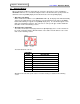
Chapter 8: Troubleshooting 8.1 enFORCE Operation Manual Abnormal Display When an abnormal condition is detected by the system, the affected press stops and lights the ABNORMAL LED. For ease of troubleshooting the nature of the abnormal, the system provides an abnormal code in the [PARM] display and an abnormal sub-code in the [D-NO] display. • Abnormal code display. When an Abnormal condition occurs (ABNORMAL LED is lit), the display mode will automatically change to the STATUS mode.
Chapter 8: Troubleshooting enFORCE Operation Manual 8.2 Load Cell Abnormals [ A1_* ] • Code A1_0 - LOAD CELL / ZERO VOLTAGE ERROR Zero level does not match master level read from tool EEPROM during power on initialization. CAUSE: 1. When the tool load cell is sensing excessive force due to forces on the press shaft. 2. If the controller or the load cell cable is located in an electric or magnetic noise field. 3. When the load cell, load cell cable or the controller malfunctions. RECOVERY: 1.
Chapter 8: Troubleshooting enFORCE Operation Manual • Code A1_3 - LOAD CELL / CAL SELF CHECK ERROR Calibration level voltage error after a press start was attempted. CAUSE: 1. When the load cell is sensing excessive force due to pressure or vibration during the press cycle start. 2. If the controller or the load cell cable is located in an electric or magnetic noise field. 3. When the load cell, load cell cable or the controller malfunctions. RECOVERY: 1.
Chapter 8: Troubleshooting enFORCE Operation Manual 8.3 Offset Load Abnormals [ A2_* ] • Code A2_0 - OFFSET LOAD ABNORMAL High load was detected during an initial stage of press. CAUSE: 1. Excessive binding in the press shaft or press fixture. 2. The load cell is sensing excessive force due to pressure or vibration during the initial stage of press cycle. 3. The controller or the load cell cable is located in an electric or magnetic noise field. RECOVERY: 1. Repair or replace mechanism which is binding.
Chapter 8: Troubleshooting enFORCE Operation Manual 8.4 Preamplifier Errors [ A3_* ] • Code A3_0 - PREAMPLIFIER / TOOL ID CHECKSUM ERROR Communication data checksum error between the load cell preamplifier and the SAN Unit. Data is not reliable due to data error. CAUSE: 1. If the controller or the load cell cable is located in an electric or magnetic noise field. 2. When the load cell, load cell cable or the controller malfunctions. RECOVERY: 1.
Chapter 8: Troubleshooting enFORCE Operation Manual 8.5 System Memory Errors [ A4_* ] • Code A4_0 - SYSTEM MEMORY ERROR / FLASH ROM WRITE ERROR Communications error to internal SAN Flash ROM during WRITE attempt. CAUSE: 1. Metal chips and/or debris have migrated inside SAN Unit through vent holes. 2. Flash ROM IC chip has malfunctioned. RECOVERY: 1. Remove SAN Unit and blow or shake out debris. 2. Replace and return unit to FEC for repair.
Chapter 8: Troubleshooting enFORCE Operation Manual 8.6 Servo Amplifier Response Errors [ A5_* ] • Code A5_0 - SERVO AMPLIFIER REPLY ERROR / NO REPLY FROM RESOLVER The controller is attempting to turn the motor, but is not receiving any signals back from the resolver to indicate that the tool is actually turning. CAUSE: 1. The motor/resolver cable is damaged or not connected 2. When the resolver, motor, or the controller malfunctions. 3.
Chapter 8: Troubleshooting enFORCE Operation Manual 8.7 Servo Type Error [ A6_* ] • Code A6_0 - SERVO TYPE ERROR / SERVO TYPE MISMATCH The SAN Unit model does not match the connected motor type. RECOVERY: 1. Verify the servo type tag with the motor type tag. 2. There are 3 types of SAN Units (controllers) available & they must be connected to the correct motor size as shown in the tables in sections 2.1 and 2.2.
Chapter 8: Troubleshooting enFORCE Operation Manual 8.8 Servo Amplifier Errors [ A8_* ] • Code A8_1 - SERVO AMPLIFIER ERROR / SERVO IS OVER HEATED The SAN controller servo circuit has overheated. CAUSE: 1. The controller servo drive circuit has failed. 2. If the environment temperature is more than 122 degrees Fahrenheit (50 degree centigrade) without any air flow. 3. Source voltage is very close to the limit (242 VAC) and the environment temperature is also close to the limit. RECOVERY: 1.
Chapter 8: Troubleshooting enFORCE Operation Manual • Code A8_6 - SERVO AMPLIFIER ERROR / INPUT VOLTAGE ABNORMAL The SAN controller servo power supply circuit has detected improper input voltage either above or below the specified limits. CAUSE: 1. The controller internal power supply has failed. 2. Source voltage is out of the limit (180-242 VAC) and/or the environment temperature is also close to the limit. 3. One or more phases of input power are missing. RECOVERY: 1. Replace the controller. 2.
Chapter 8: Troubleshooting enFORCE Operation Manual 8.9 Parameter Errors [ A9_* ] • Code A9_0 - PARAMETER ERROR / MISSING SPEED PRESET Some speed preset is not set up in the parameter number selected or the wrong parameter number has been selected by the PLC. RECOVERY: 1. Verify that the parameter number that is being selected by the PLC is configured in the controller. 2. Check that the speed presets are not <0> or out of the specified speed range of the tool.
Chapter 8: Troubleshooting enFORCE Operation Manual • Code A9_6 - PARAMETER ERROR / DISTANCE SETUP ERROR One of the Distance presets is out of range RECOVERY: 1. Verify that the Distance presets are in range for the tool size. 2. Check that the Distance presets are not <0> or setup as specified in 6.4.5.2. • Code A9_7 - PARAMETER ERROR / MANUAL OR RETURN LOAD OVER. The Manual or Return Load is more than 1/6 of the Full Scale Load. RECOVERY: 1.
Chapter 8: Troubleshooting enFORCE Operation Manual 8.10 Questions & Answers Q1: Does home position search have to be performed every time the power is turned on? A1: Yes. Home position search should also be performed after an abnormal has occurred. Q2: REJECT was output but the reason in unclear. A2: See “Operation Result Display Mode” in Section 6.3.5. Contents of the REJECT is shown from ‘ 6’ to ‘ 9’. Q3: Is it possible to press while jogging in Manual Mode? A3: No.