enFORCE DSP1500 SAN Unit Operation Manual (for Firmware Version 3.x) SECOND Edition January 2010 Automation Systems 51327 Quadrate Drive Macomb, MI. 48042 Web: www.fec-usa.com Phone: (586) 781-2100 Fax: (586) 781-0044 E-mail: support@fec-usa.
Revisions Revision Revision Date 3 11/2007 3.1 4 Firmware Version* Revision History 3.14 Initial Release Minor Revision Chapter 2 - Updated chart for new power requirements. 10/2008 Chapter 4 - Updated transformer sizing chart based on new power requirements. Added functionality for SAN4 Controller. Added functionality for DPM & DPS Series presses. 01/2010 Chapter 6 - Added Real Time Clock functionality for new SAN3-DP1/2S keypad display. Chapter 7 - Expanded on lubrication requirements. 3.
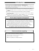
Introduction Thank you for purchasing our Electric Servo Press - DSP1500 System. This instruction manual describes the procedures for installation, wiring, handling and actions to be taken in case of any failure. ◆ This instruction manual shall be delivered to the end user who operates the equipment. ◆ Read all instructions before use and always keep this instruction manual with the equipment. ◆ Items not described in this instruction manual shall be considered “unavailable”.
Introduction Warranty Warranty Period The standard warranty period is one year from the date of purchase or one year from delivery to the designated End User (not to exceed 18 Months). Actual terms are order specific. Provision of warranty If at any time during the warranty period your product proves to be defective, it will be repaired free of charge as long as it was used properly in accordance with this instruction manual.
Safety Precautions Read all instructions before operating the equipment in order to use this equipment safely and correctly. Read this instruction manual carefully and fully understand the equipments functions, safety precautions and instructions prior to using the equipment. Safety precautions in this manual are marked with two symbols [Warning] and [Caution].
Safety Precautions Warning Never touch press ram during operation. Failure to do so may cause injury. Make sure that no part of your body gets near any moving part of the tool even while the equipment is at rest. The press ram may lower for some reason resulting in injury. When performing maintenance or inspection, be sure to secure the press ram with safety blocks to prohibit the ram from lowering. Do not remove the motor and gear case of tool. The press ram may lower resulting in injury.
Safety Precautions Transportation / Storage Caution Transport the equipment properly according to its weight. Failure to observe this instruction may cause injury and malfunction. The conditions when transporting the equipment by ship is as below. ◆Ambient temperature: -5°C~+55°C (Avoid freezing) ◆Ambient humidity: 50% RH or lower (Avoid moisture) ◆Package: Tight seal ◆Rust prevention measure: Apply grease or oil on tools. Failure to observe this instruction may cause earth leakage and malfunction.
Safety Precautions Installation / Wiring Caution Install the tools in a place that can support the weight and maximum load during operation. Failure to observe this instruction may cause injury and malfunction. Install the SAN Unit firmly inside the control panel using the specified screws. Failure to observe this instruction may cause malfunction. Use the specified tool for the SAN Unit. Failure to observe this instruction may cause fire and malfunction.
Safety Precautions Operation / Adjustment Caution Never operate the equipment with wet hands. Failure to observe this instruction may cause electric shock. Keep fingers away from the SAN Unit radiating fins and tool motor while the equipment is turned ON or for a while after the equipment is turned OFF. These parts may become very hot. Failure to observe this instruction may cause burns. Use the equipment under the following conditions.
Table of Contents Chapter 1: 1.1 1.2 1.3 1.4 Outline About this Operation Manual ..…..………………………………………………1-2 Features ………………………………………………………………………….. 1-3 Safety Precautions …. ………………………………………………………….. 1-4 Safety Labels................................................................................................ 1-5 Chapter 2: Specifications 2.1 System Specifications …..………………………………………………………. 2-2 2.2 SAN Unit Specifications …… ………………………………………………….. 2-3 2.2.1 Duty Cycle Calculation ..……………………..
Table of Contents 4.9 MON. Signal (External Monitor Signal) ……………………………………….. 4-24 4.9.1 Calibration Method for External Monitoring Equipment..……………….. 4-25 4.10 RS-485 Interface Signal ………………………………………………………… 4-26 4.11 Firmware Flash Connector....…………………………………………..……….. 4-27 4.12 Cable Installation Guidelines...………………………………………………….. 4-28 4.12.1 Considerations for Cable Trolleys …………………………………………. 4-29 4.12.2 Considerations for Flexible Cable Track ………………………………….. 4-29 4.12.
Table of Contents Judgment Operation......................................................................... 6-44 Loading Direction…......................................................................... 6-44 Return Operation………................................................................... 6-45 Step Press Using Time Controlled Press......................................... 6-46 Return Parameter Setup………………............................................. 6-47 Chapter 7: Maintenance & Inspection 7.
Table of Contents Appendix A: Reference Drawings Power Wiring Reference (SAN3).…………………………………………………….. A-2 Power Wiring Reference (SAN4).…………………………………………………….. A-3 Standard Transformers………………………………… …………………………….. A-4 Motor/Resolver Homerun Cable (DPT & DPS) - (RM1, RM2 & RM3 Motor)….… A-5 Motor/Resolver Homerun Cable (DPT & DPS) - (RM4 Motor).…..….……………. A-6 Motor Homerun Cable (DPT & DPS - (RM5 Motor).…..................….……………. A-7 Resolver Homerun Cable (DPT & DPS) - (RM5 Motor)….............….…………….
Blank Page (Rev.
Chapter 1: Outline PAGE 1-1
Chapter 1: Outline 1.1 enFORCE DSP1500 SAN Unit Operation Manual About this Manual This manual details the configuration, specifications and operation of the enFORCE Digital Servo Press System. This manual is written for SAN Units with Firmware Version 3.x. If you have a SAN Unit with an earlier version, do not use this manual as reference. The following table outlines the contents of each chapter. Title Chapter Contents Basic characteristics and requirements of the enFORCE System.
Chapter 1: Outline enFORCE DSP1500 SAN Unit Operation Manual 1.2 Features enFORCE is a Digital Servo Press System designed for use in both pressing and bonding applications in a low cost package. The system is a culmination of over thirty years of servo motor expertise based on our electric fastening system integrated with the latest digital servo technology. ☆ Compact Design As the result of miniaturization circuit technology, the compact units maintain a maximum width of 123.
Chapter 1: Outline enFORCE DSP1500 SAN Unit Operation Manual 1.3 Safety Precautions To ensure the most effective and extended use of all equipment, adhere to the following precautions: ¾ Tool Installation • The tool generates a great amount of force during operation and the reaction force is applied to the mounting area of the tool. Therefore, tools must be installed in the proper position and with adequate bolts.
Chapter 1: Outline enFORCE DSP1500 SAN Unit Operation Manual ¾ Electrical Noise Prevention • SAN units must be located a minimum of 600mm from high transient voltage sources such as transformers, motor starters, AC inverters and AC contactors. If it cannot be avoided, the unit must be shielded. • If high powered devices are used inside the enclosure, they must use a surge suppression device.
Chapter 1: Outline enFORCE DSP1500 SAN Unit Operation Manual SAN3-24S SAN3-120S (Rev.
Chapter 2: Specifications PAGE 2-1
Chapter 2: Specifications enFORCE DSP1500 SAN Unit Operation Manual 2.
Chapter 2: Specifications enFORCE DSP1500 SAN Unit Operation Manual 2.2 SAN Unit Specifications 32 bit RISC (Reduced Instruction Set CPU) RS485 (2 Ports) – 1 for DSP User Console Software Flash ROM CPU: Data Communication: Parameter / Firmware Storage: SAN Unit Type SAN3 - 24HS SAN4 - 24HS Motor Type RH1 SAN3 Unit Input Power SAN4 Unit Motor Power SAN Unit Frequency Max.
Chapter 2: Specifications 2.2.2 enFORCE DSP1500 SAN Unit Operation Manual SAN Unit Dimensions SAN3/4-24S, SAN3/4-24HS, SAN3/4-40S Mounting: Top Bottom 1 place 2 places #8-32 screw #8-32 screw Weight: SAN3/4-24S, 24HS - 1.4 kg SAN3/4-40S - 1.8 kg Note: The diagram shown above reflects dimensions for the SAN3/4-40S. The SAN3/4-24S and SAN3/4-24HS do not have a heat sink plate so the width is 60mm as opposed to 74mm. (Rev.
Chapter 2: Specifications enFORCE DSP1500 SAN Unit Operation Manual SAN3/4-120S Mounting: Top Bottom 2 places #8-32 screw 2 places #8-32 screw Weight: SAN3/4-120S - 3.6kg. PAGE 2-5 (Rev.
Chapter 2: Specifications enFORCE DSP1500 SAN Unit Operation Manual 2.3 Press Tool 2.3.1 Part Number Breakdown [DPT]-[151]R[3][ ]-[25][F][S][B]-[00][A] A B CD E F G H I J (Rev. 4) (A) PRESS SERIES ( )DPT = STANDARD (*)DPM = MINI SERIES (500 & 1000N) (**)DPS = SLIM-LINE SERIES (1, 3 & 5ton) (B) PRESS FORCE (In Metric Tons) 050=0.05ton * 011=0.1ton * 021=0.2ton 051=0.5ton 101=1.0ton ** 151=1.
Chapter 2: Specifications enFORCE DSP1500 SAN Unit Operation Manual 2.3.2 Tool Specifications Motor: Force Monitor: Distance Monitor: Permanent magnet DC Inline Load Cell High Resolution Resolver List of standard tools for press-fitting (F type) - Use when operating with instantaneous load. Tool No. Tool type Maximum load [KN] Maximum speed Minimum speed [mm/sec] [mm/sec] 114 DPM-011H1-**F 1.000 130.0 0.4 30 DPT-021R1-**F 1.96 416.6 0.4 31 DPT-051R2-**F 4.90 333.3 0.
Chapter 2: Specifications 2.3.
Chapter 2: Specifications enFORCE DSP1500 SAN Unit Operation Manual 2.4 Functions • Pressing Function The following press control methods can be selected for the enFORCE System. 1. 2. 3. 4. 5. 6. 7. 8. 9. Load Control Distance Control Specified Point Load Judgment Load Rise Detection Specified Range Peak Load Judgment Time Controlled Press Load Drop Detection Load Drop Detection (Point Stop) Distance Control with Load Limit Load and Distance can be monitored in any configuration.
Chapter 2: Specifications enFORCE DSP1500 SAN Unit Operation Manual Blank Page (Rev.
Chapter 3: System Description PAGE 3-1
Chapter 3: System Description enFORCE DSP1500 SAN Unit Operation Manual 3.1 System Block Diagram (Main Unit Configuration) (Stand Alone Configuration) ♦ The enFORCE system can consist of a single unit or combined in multiple press configuration controlled by one main controller (Main Unit) using one set of I/O to control the group of presses. Discrete 24VDC (Sinking) I/O on the SAN unit provides direct communication with the PLC for individual press control (Stand Alone).
Chapter 3: System Description enFORCE DSP1500 SAN Unit Operation Manual 3.2 DSP1500 SAN Unit Front Panel 3.2.1 SAN Unit Front Panel Switches and Connectors D SP1500 CON1 P OWE R SW1 CON1: For Display Unit (SAN3-DP*S) connection. SW1: Sets press number and special configuration features.(See Section 4.8) RUN/BYPASS: RUN: BYPASS: Controller Enable/Disable switch. Enable Bypass Mode(Disable) RS485: Bi-directional Communication ports. RESOLVER: Resolver connection for tool Motor/Resolver cable.
Chapter 3: System Description 3.2.2 enFORCE DSP1500 SAN Unit Operation Manual SAN Unit Front Panel Condition Display LED’s DSP150 0 POWER LED (Yellow) Lights when 180~242VAC input power is applied to the controller. CON1 SW1 POWER BUSY SV. BYP AS S R UN BUSY LED (Orange) Lights up when in cycle Blinks when returning Blinks when running in MANUAL Lights up when powering on and initializing ABN. ACC . REJ . RS 4 85 SV. [SERVO] LED (Red) Lights up when a servo amplifier fault condition exists. ABN.
Chapter 3: System Description enFORCE DSP1500 SAN Unit Operation Manual 3.2.3 SAN Unit Detachable Keypad Buttons S T A R T M A NU A L CA L ( S E A RC H) RESET Operating Button START Button MANUAL Mode (Jog) Button CAL Button RESET Button DAT A D S P1 5 0 0 D - NO PARM M O DE D AT A S ET ( H O M E) BYP AS S R UN Data Display / (Operating) Button MODE Button SET Button(Home Return) DATA UP Cursor Button(Manual Jog Return) DATA DOWN Cursor Button (Manual Jog Advance) AB N. ACC . REJ .
Chapter 3: System Description 3.2.4 enFORCE DSP1500 SAN Unit Operation Manual SAN Unit Detachable Keypad Condition Display S T A R T M A NU A L CA L ( S E A RC H) RESET DATA Display (4 figure) Data Display (Load, Distance, etc.) DAT A PARM Display (2 figure) Parameter Number Display Or Abnormal Number Display D S P1 5 0 0 D - NO PARM M O DE D AT A S ET ( H O M E) BYP AS S R UN D-NO Display (2 figure) Data Number Display Press Unit Number Display Or Abnormal Sub-Code Number Display AB N. ACC .
Chapter 3: System Description enFORCE DSP1500 SAN Unit Operation Manual 3.3 Press Tool Drawing Shown For Reference Only A) MOTOR: Totally enclosed DC permanent magnet motor Refer to Chapter 2 for available motor sizes B) RESOLVER: Provides feedback for speed regulation to servo amplifier Provides distance monitoring capability to press operation C) PRE-AMPLIFIER: Amplifies load transducer signal. Houses “I.D.
Chapter 3: System Description enFORCE DSP1500 SAN Unit Operation Manual 3.4 Connection Diagrams Brake Cable DPT Series SAN Unit Tool CCW Motor ※ORG Resolver PC, PLC or Main Unit Resolver Cable CW Monitor Signal Motor Cable PLC Customer Supplied I/O Cable Power Cable SAN4 Contactor Noise Filter Circuit Protector 180~242VAC LMT ※On SAN4 Only Control Power Cable Limit Sensor Cable Preamplifier Cable NOTE: 1. Origin Sensor (ORG) is used on 10, 15 and 20 ton presses. 2.
Chapter 3: System Description enFORCE DSP1500 SAN Unit Operation Manual DPS Series Brake SAN Unit Tool CCW Preamplifier Motor Resolver PC, PLC or Main Unit Resolver cable Monitor Signal Motor cable Customer Supplied PLC I/O Cable Power Cable SAN4 Contactor Noise Filter Circuit Protector 180~242VAC LMT ※On SAN4 Only Control Power Cable Limit Sensor / Brake Cable Preamplifier Cable Brake Cable BRK NOTE: 1. Clockwise Sensor (CW) is not used in this series. 2.
Chapter 3: System Description enFORCE DSP1500 SAN Unit Operation Manual DPM Series SAN Unit Tool Cable Tool Motor Resolver Preamplifier PC, PLC or Main Unit Monitor Signal PLC Customer Supplied Power Cable SAN4 Contactor Noise Filter Circuit Protector 180~242VAC SAN324HS ※On SAN4 Only Control Power Cable NOTE: 1. Clockwise and Counter-clockwise Sensors/cables (CCW & CW) are not used in this series. 2. Motor, Resolver and Transducer (Load Cell) cables are combined into 1 cable. 3.
Chapter 4: System Setup & Wiring PAGE 4-1
Chapter 4: System Setup and Wiring enFORCE DSP1500 SAN Unit Operation Manual 4.1 Design and Build Guidelines Review Chapters 1 and 2 prior to designing a System. If requirements and specifications in these two chapters are not addressed, there is a possibility for degraded system performance. № ITEM COMMENTS Section Reference 1 Select the correct tool size Keep force range between 50% and 75% of tool capability for press performance. 2 Design tool mounting plate and press fixtures.
Chapter 4: System Setup and Wiring enFORCE DSP1500 SAN Unit Operation Manual 4.2 SAN Unit Design and Mounting Dimensions SAN units must be mounted with a minimum clearance of 12mm on each side to allow proper heat dissipation. Cable connections on the front of the units require 100mm of clearance. Allow a minimum of 100mm clearance on the bottom of each controller for SAN4 control power connection and for flash connector hook up when updating firmware.
Chapter 4: System Setup and Wiring enFORCE DSP1500 SAN Unit Operation Manual SAN3/4-120S Mounting: Top (2) places Bottom (2) places Weight: SAN3/4-120S - (Rev. 4) #8-32 screw #8-32 screw 3.
Chapter 4: System Setup and Wiring enFORCE DSP1500 SAN Unit Operation Manual 4.3 Calculating Circuit Protection RATED VALUES FOR MOTOR MOTOR TYPE WATTAGE R1 60 R1H 70 R2 80 R3 200 R4 1500 R5 3000 CALCULATING CIRCUIT PROTECTION # OF SAN3/4 UNITS KVA PER SAN3/4 UNIT PER 1 KVA SAN3/4 UNIT SAN3/4-24S 10 .100 SAN3/4-24HS 8 .125 SAN3/4-24S 8 .125 SAN3/4-40S 6 .166 SAN3/4-120S 3 .333 SAN3/4-120S 1.5 .
Chapter 4: System Setup and Wiring enFORCE DSP1500 SAN Unit Operation Manual 4.4 Input Power Supply Connection(s) On SAN3 Units, Motor and Control input power is supplied on one connector. On SAN4 Units the Motor and Control input power can be separated. This allows the removal of motor power without the press losing its Home Position. Adequate circuit protection must be provided for the SAN unit input power. 4.4.
Chapter 4: System Setup and Wiring enFORCE DSP1500 SAN Unit Operation Manual 4.4.2 Input Control Power Connection (SAN4 Only) Recommended conductor size should be a minimum of #16AWG. Suggested color code (FEC standard): U – Red, V – White, FG – Green. SAN4-24S, 24HS, 40S SAN4-120S Wiring Chart 3:U 2:V 1:FG 1-Phase 180 ~ 242VAC 50/60Hz. Mating Connectors Manufacture: Housing Part No.: Contact Part No.: PAGE 4-7 AMP 1-178128-3 1-175218-3 (Qty.-3) (Rev.
Chapter 4: System Setup and Wiring enFORCE DSP1500 SAN Unit Operation Manual 4.5 Motor Power-Resolver Connections The motor connector provides control power to the motor. The resolver connector handles the signals that define the rotation of the motor. The controller provides a signal to the winding of the rotor. As the rotor spins, two sets of stators electrically shifted 90 degrees, generate a sine wave and a cosine wave signal.
Chapter 4: System Setup and Wiring enFORCE DSP1500 SAN Unit Operation Manual 4.6 Pre-Amplifier Connection The pre-amplifier connector links the SAN controller to the tool load cell in order to perform the following functions: 1. Reads the load voltage values from the pre-amplifier. 2. Tests the pre-amplifier condition by generating a voltage signal for full scale load by the Calibration function. 3. Tests the Pre-amplifier Zero level by the Zero Level Check function. See Section 4.
Chapter 4: System Setup and Wiring enFORCE DSP1500 SAN Unit Operation Manual 4.7 External-Control Signal Connection Mating Plug Manufacturer:Honda Tsushin Kougyo (HONDA) Vertical Housing Part No.: MR-34L Male Insert Part No.: MR-34M (See Appendix A for connecting cable part numbers) 4.7.1 PLC Interface (I/O ) Signals [Main Unit Configuration] Pin No.
Chapter 4: System Setup and Wiring enFORCE DSP1500 SAN Unit Operation Manual 4.7.2 PLC Interface (I/O) Signals [Stand Alone Configuration] Pin No.
Chapter 4: System Setup and Wiring enFORCE DSP1500 SAN Unit Operation Manual *Allow at least 20ms from the time the desired bank is selected before reading the OUT DATA signal. BANK1 OFF OFF ON ON (Rev. 4) BANK0 OUT DATA Signal Name OFF OUT DATA0 OUT DATA1 OUT DATA2 OUT DATA3 OUT DATA4 OUT DATA5 OUT DATA6 OUT DATA7 OUT DATA8 OUT DATA9 OUT DATA10 OUT DATA11 SERVO ON HOME SET PRESS RET’D BUSY READY ABNORMAL ACCEPT REJECT ADVANCED ADV / RET POS.
Chapter 4: System Setup and Wiring enFORCE DSP1500 SAN Unit Operation Manual 4.7.3 Input and Output H/W Recommended Connecting Circuit DSP1500 SAN UNIT PLC OUTPUT 40mA Max. OUTPUT PLC CONNECTOR 40mA Max. INPUT INPUT 24 VDC All SAN Unit inputs and outputs are active true low. All interface devices must accommodate active true low connection (NPN) for correct operation.
Chapter 4: System Setup and Wiring 4.7.4 ♦ enFORCE DSP1500 SAN Unit Operation Manual Input and Output Signal Explanation Input Signals Inputs are sourced (normally high) and activated when pulled low (0VDC). STOP: Emergency Stop signal (Normally Closed) This signal must be active (on) for controller operation. When it is inactive (off), controller operation will stop, press motion stops and input/outputs will be disabled.
Chapter 4: System Setup and Wiring enFORCE DSP1500 SAN Unit Operation Manual BYPASS: Press off signal (Normally Open) When active (on), all functions of the press controller are disabled and a BYPASS signal is output, making it impossible to start the press. If the signal becomes active during a press cycle, the press cycle is stopped. NEAR ORIGIN: Near Home sensor signal (Normally Open) Used in special applications on 10 ton and larger presses. It is only used when performing a Home Position Search.
Chapter 4: System Setup and Wiring enFORCE DSP1500 SAN Unit Operation Manual WORK SELECT 0 thru 4: Parameter Select signal (Normally Open) These 5 inputs [WORK SELECT 0-4] form a binary code which is capable of selecting up to 32 different sets of press parameters. *Allow at least 10ms from the time this signal is turned on before turning on the START signal. Do not turn this signal off at least until BUSY goes “HIGH”. WORK WORK WORK WORK WORK Param MANUAL mode No.
Chapter 4: System Setup and Wiring enFORCE DSP1500 SAN Unit Operation Manual ♦ Output Signals Outputs are rated at +12~24VDC, 200ma. When activated, open collector sink outputs (normally high) pull the input device low (0VDC). OUTPUT BANK 1: Bank0 – Off / Bank1 - Off SERVO ON: [OUT DATA0 - PIN #24] Servo Running Signal Output when the servo is running. This signal will turn OFF when a reset is input. May be used to monitor when to engage/disengage the maintenance brake (See Section 4.14).
Chapter 4: System Setup and Wiring enFORCE DSP1500 SAN Unit Operation Manual PRESS ADVANCED: [OUT DATA8 - PIN #32] Outputs when the press reaches the target load or target distance for a time that is set in [61: Load Hold Time]. Í If Load Hold Time is set to zero the PRESS ADVANCED signal will not turn on. TIMING SIGNAL: [OUT DATA9 - PIN #33] (Advance / Return Position Signal Output) Data Numbers 50, 51, 52 and 53 of Parameters 1~32 are used to set ON and OFF limits for the Timing Signal.
Chapter 4: System Setup and Wiring enFORCE DSP1500 SAN Unit Operation Manual OUTPUT BANK 2: Bank0 – On / Bank1 - Off WORK SELECT 4: [OUT DATA3] Work Select 4 Input Echo Signal Output when the WORK SELECT 4 input is high (On). WORK SELECT 3: [OUT DATA4] Work Select 3 Input Echo Signal Output when the WORK SELECT 3 input is high (On). WORK SELECT 2: [OUT DATA5] Work Select 2 Input Echo Signal Output when the WORK SELECT 2 input is high (On).
Chapter 4: System Setup and Wiring enFORCE DSP1500 SAN Unit Operation Manual CK2_HIGH: [OUT DATA7] Part Check 2 High REJECT Signal Output when the load sensed by the press between Part Check 2 Start Distance and Part Check 2 End Distance is above the acceptable Part Check 2 Load High Limit. Output remains active until the start or reset signal is input.
Chapter 4: System Setup and Wiring enFORCE DSP1500 SAN Unit Operation Manual 4.7.5 Operation Timing Chart Automatic Mode Timing to set the START signal When the START or RESET signal OFF, it is voluntary if the BUSY is is turned ON the ACCEPT and OFF. REJECT signals turn OFF.
Chapter 4: System Setup and Wiring enFORCE DSP1500 SAN Unit Operation Manual 4.8 SW1 - SAN Unit DIP Switch Settings 4.8.1 SAN Unit Address Settings (DIP Switch 4~8) In a multiple SAN Unit system, it is necessary to address each unit for communication purposes. The number is set with the front DIP switch (4 thru 8) of the SAN Unit. If the display unit is installed, it must be removed to access the DIP switches. No two units can share the same number.
Chapter 4: System Setup and Wiring enFORCE DSP1500 SAN Unit Operation Manual 4.8.2 Special Configuration Settings (DIP Switch 1~3) 1 ON: CAL/Zero acceptance window = +/-10% of full scale load. OFF: CAL/Zero acceptance window = +/-4% of full scale load. (Default) 2 ON: Parameter changes made by communicating are not saved on EEPROM. OFF: Parameter changes made by communicating are saved on EEPROM.
Chapter 4: System Setup and Wiring enFORCE DSP1500 SAN Unit Operation Manual 4.9 MON. Signal (External Monitor Signal) This auxiliary connector is used to output Load, Position, Current and Speed signals to external equipment for monitoring purposes. This connection is not required for the system to operate. enFORCE outputs 1 digital pulse per 0.1mm moved distance and press proportionate to load by the MON>OUT connectors.
Chapter 4: System Setup and Wiring enFORCE DSP1500 SAN Unit Operation Manual 4.9.1 Calibration Method for External Monitoring Equipment When the CAL switch on the SAN unit display is pressed, load voltage is outputted on the LOAD OUT at a potential difference of approximately 2.5V. The load value which the SAN unit recognizes at this time is displayed on the DATA display. Make adjustments so that the load value that is displayed at this load voltage is the same as the external monitoring equipment.
Chapter 4: System Setup and Wiring enFORCE DSP1500 SAN Unit Operation Manual 4.10 RS485 Interface Connection The enFORCE system communication is performed via the RS485 port. These ports are provided to link each SAN Unit together by “jumpering” from one controller to the next or for connecting to the Main Unit. Both connectors are identical and are internally connected. There is no order (upper or lower connection) in how the cables must be connected from SAN Unit to SAN Unit.
Chapter 4: System Setup and Wiring enFORCE DSP1500 SAN Unit Operation Manual 4.11 Firmware Flash Connector (CN8) Upgrades or revisions to Firmware are handled easily with the on board Flash connector located on the bottom of each SAN Unit. There is no need to remove or disassemble the unit. A Flash adapter (SAN-ROM) containing the new firmware can be connected to connector CN8 with the power off to the unit.
Chapter 4: System Setup and Wiring enFORCE DSP1500 SAN Unit Operation Manual 4.12 Cable Installation Guidelines Improper installation of cables can reduce cable life expectancy drastically. The following guidelines should be used when installing cables. • The cables must be prepared for installation without twists, bends or kinks. Upon unpacking the cables, any tie wraps used in shipping should be removed.
Chapter 4: System Setup and Wiring enFORCE DSP1500 SAN Unit Operation Manual 4.12.1 Considerations for Cable Trolleys • Cables hung by festooning type systems must be secured to the individual cable trolley and positioned to avoid sharp bends and eliminate or minimize any torsion twisting. • Restraint cords should be used in between cable trolleys to limit movement and reduce the stress on cables as they are extended.
Chapter 4: System Setup and Wiring enFORCE DSP1500 SAN Unit Operation Manual 4.13 Tool Connections Tools are connected to the SAN controller using three or four cables. The first cable connects to the Load Cell Force Transducer preamp. Second is a combination Motor / Resolver Cable. The third cable connects the position proximity switches for home and advanced position indication. A fourth cable is for an external brake (maintenance lock) if ordered.
Chapter 4: System Setup and Wiring enFORCE DSP1500 SAN Unit Operation Manual 4.14 Maintenance Lock Option Power Requirements Voltage 24VDC to disengage brake RM1 Motor RM2 Motor Current Consumption RM3 Motor RM4H Motor RM5 Motor 0.5A 0.5A 0.5A 0.8A 1.2A Press Reference Circuit red/grn BRK Varister Brake blu/grn A B RY 24V 0V SAN Unit PLC I/O Connector Y001 RELEASE BRAKE 24 X000 SERVO ON SERVO ON *PLC I/O shown for reference only.
Chapter 4: System Setup and Wiring enFORCE DSP1500 SAN Unit Operation Manual Blank Page (Rev.
Chapter 5: Power Up & Initial Checks PAGE 5-1
Chapter 5: Powering Up and Initial Checks enFORCE DSP1500 SAN Unit Operation Manual WARNING DO NOT operate the press WITHOUT all safety guards and/or devices in place and operational. NEVER enter the press ram area with power applied to the press unit. Follow Lockout/Tagout and other safety precautions when performing maintenance or connecting / disconnecting cabling, wiring, and equipment. There is a possibility of receiving an electrical shock from this equipment, if used improperly. 5.
Chapter 5: Powering Up and Initial Checks enFORCE DSP1500 SAN Unit Operation Manual 5.2 Initial Data Setting (Display Module Required) After the previous items have been completed, turn on the power supply and then verify that the SAN Units are set with the correct function version. This number is set in System Parameter 00-03. (See section 6.3.6 and 6.4.
Chapter 5: Powering Up and Initial Checks enFORCE DSP1500 SAN Unit Operation Manual Blank Page (Rev.
Chapter 6: System Operation PAGE 6-1
Chapter 6: System Operation enFORCE DSP1500 SAN Unit Operation Manual 6.1 Display and Programming Unit An optional detachable display / programming unit is available for the SAN Unit. The display unit allows the viewing of press results as well as viewing / programming of press parameters if the DSP software is not being used. SAN3-DP1S SAN3-DP2S (RS-232) The DP2S has the same functionality as the DP1S with the added function of a serial RS-232 port for output of press data from the associated SAN Unit.
Chapter 6: System Operation enFORCE DSP1500 SAN Unit Operation Manual 6.1.1 DP2S Serial Connection Connector: DB-9P (Male) Mating Connector: DB-9S (Female) PIN No. Signal 1 2 Signal Description Not Used RXD Not Used 3 TXD Output data for printer 4 DTR ON output (always) 5 GND Signal ground 6 Not Used 7 RTS ON output (always) 8 CTS Connects to DTR signals such as printers 9 Not Used The CTS signal needs to be activated in order for the press data to be output.
Chapter 6: System Operation enFORCE DSP1500 SAN Unit Operation Manual 6.1.2 RS-232C Output Data Result data is output every time the operation is finished. The result output is possible for each unit that has a SAN3 –DP2S installed.
Chapter 6: System Operation enFORCE DSP1500 SAN Unit Operation Manual Data format when the judgment is a REJECT 1 2 3 4 5 6 7 8 9 20H Cycle Count 10 11 Press Number 30H 31H 12 15 16 20H 20H 30H 30H 30H 30H 30H 30H 30H 31H 0 0 0 0 0 0 0 1 17 18 19 22 23 Judg ment 34H 48H 20H 24 31H 32H 4 H 1 2 38 39 Judg ment 34H 20H 20H 40 41 31H 32H 33H 2EH 34H 35H 47 Judg ment 36H 20H 4 1 2 3 . 4 5 6 56 Judg ment 5AH 57 58 59 60 61 62 . 3 4 76 77
Chapter 6: System Operation enFORCE DSP1500 SAN Unit Operation Manual 6.2 Function of Display and Operating Panel Manual Operation Buttons [START]: Cycle START Button Pressing this button initiates the press cycle. The press will perform the operation as defined in the active parameter while pressing. This button must be held until the press cycle ends. If the button is released in the middle of the operation, the press will stop and, if programmed to do so, will return.
Chapter 6: System Operation enFORCE DSP1500 SAN Unit Operation Manual 6.3 RUN Status Mode Operating Instruction The enFORCE System has two operational states which are selected with the RUN/BYPASS switch on the front of the SAN Unit or by the PLC Bypass input. When the RUN/BYPASS switch is in the RUN position or when the PLC Bypass input is low (OFF), the unit is in RUN status. In the RUN status, press results, abnormalities and preset values are displayed. 6.3.
Chapter 6: System Operation enFORCE DSP1500 SAN Unit Operation Manual 6.3.2 Mode Change Three display modes can be selected while in the RUN state by pressing the [MODE] button. In addition, the values of each mode can be scrolled through by pressing the [↑] and [↓] buttons. When the unit powers on, the display defaults to the Real Time Display Mode. When the press cycle starts, the display switches to the Operating Condition Display until the end of cycle.
Chapter 6: System Operation enFORCE DSP1500 SAN Unit Operation Manual 6.3.3 RUN Status Key Operation Selecting [Real Time Display Mode], [Press Result Display Mode] and [Parameter Display Mode] is possible by pressing the [MODE] button. When the press is operating, the [Operating Condition Display] is displayed.
Chapter 6: System Operation enFORCE DSP1500 SAN Unit Operation Manual 6.3.4 Real Time Display Mode D-NO: 1 Digit Display The following data is displayed on the screen in the Real Time Display Mode. The [D-NO] changes by pressing the [↑] and [↓] buttons. D-NO 0 1 2 DATA Load value display Displays present load applied on the load cell in real time. Load voltage value display Displays present load signal voltage applied on the load cell in real time.
Chapter 6: System Operation enFORCE DSP1500 SAN Unit Operation Manual 6.3.5 Press Result Display Mode D-NO:Digit on the Left The following is displayed on the screen in the Press Result Display Mode. The [D-NO] changes by pressing the [↑] and [↓] buttons.
Chapter 6: System Operation 6.3.6 Parameter Display Mode enFORCE DSP1500 SAN Unit Operation Manual D-NO: 2 Digit Display The following data is displayed on the screen in the Parameter Display Mode. By pressing the [↑] and [↓] buttons, the [D-NO] changes and the value of the data number is displayed in the [DATA] area. If [↓] is pressed at the first data number of each parameter number, [PARM] parameter number will increment by 1.
Chapter 6: System Operation enFORCE DSP1500 SAN Unit Operation Manual 6.3.7 Operating Condition Display The following speed conditions are shown on the display when in automatic operation: ■ Slow Start Speed ■ Approach Speed ■ Part Search Speed ■ Press Speed 2 ■ Decompression ■ Return ■ Press Speed 1 The following speed conditions are shown on the display when in Jog (Manual) operation.
Chapter 6: System Operation enFORCE DSP1500 SAN Unit Operation Manual 6.4 BYPASS Mode Operating Instruction When the RUN/BYPASS switch is moved to the BYPASS position or when a Bypass signal is received from a PLC the BYPASS led will blink and the unit will be in the BYPASS state. In this state, the Press Unit number (U.01 to 32) is displayed on the screen. 6.4.
Chapter 6: System Operation enFORCE DSP1500 SAN Unit Operation Manual 6.4.2 Data Edit Mode Immediately after entering the “Data Edit Mode”, the cursor (blinking number) is displayed in the left most digit on the “DATA” display (DATA ①). Each time the [MODE] button is pressed, the cursor (blinking character) will shift to the right.
Chapter 6: System Operation enFORCE DSP1500 SAN Unit Operation Manual 6.4.3 Parameter Copying To speed data entry, it may be beneficial to copy from one parameter set to another parameter set. This is especially convenient in the case where minor changes must be made to parameters sharing common data.
Chapter 6: System Operation enFORCE DSP1500 SAN Unit Operation Manual 6.4.4 Organization of Parameters This system is capable of storing up to 32 different parameters for pressing. System Parameter (Parameter 0) The common settings used for Parameters 1 to 32 Load Unit [KN/KLBS/TON] Dynamic Hold SP Version Manual Speed Preamp Version Tool Type No Load Current Special Settings, etc.
Chapter 6: System Operation enFORCE DSP1500 SAN Unit Operation Manual 6.4.5 Data Number Definitions 6.4.5.1 System Parameter: Parameter Number 0 0 Item System Tool Data (No Change) Tool Type System Real Time Clock PARAMETE RPARM 00 00 00 00 00 00 00 00 00 00 00 00 00 00 00 00 00 00 00 00 00 00 00 00 00 00 00 DATA NO.
Chapter 6: System Operation enFORCE DSP1500 SAN Unit Operation Manual ¾ Data number 0 4 Off Set Load [-(Calibration Load x 0.1) ~ Calibration Load] This setting is used when there is heavy tooling attached to the tool that would require added load for the press operation. If it requires 5KN to move the tooling, set at 5. The press will see the 5KN as 0 and control the operation accordingly *Do not use if the tooling is free hanging and pulling on the press ram.
Chapter 6: System Operation enFORCE DSP1500 SAN Unit Operation Manual ¾ Data Number 2 0 Tool Number The connected tool number is set from the following tool table. Tool Number Tool Name (F-Type) 30 31 32 33 43 42 40 41 37 38 39 80 81 DPT-021R1-**F DPT-051R2A-**F DPT-101R3-**F DPT-151R3-**F DPT-201R3-**F DPT-301R4H-**F DPT-501R4H-**F DPT-701R4H-**F DPT-102R5-**F DPT-152R5-**F DPT-202R5-**F DPT-501R5C-**F DPT-202R5A-**F Tool Number Tool Part No.
Chapter 6: System Operation enFORCE DSP1500 SAN Unit Operation Manual ¾ Data Number 30 Home Position Search Time Out [0 ~ 999.9 sec.] It sets the time limit of the home position search operation. The default setting is 120.0. *If the operation has not finished within the time limit an abnormal will occur and the Reject light will flash. ¾ Data number 31 Home Position Search Speed [Tool minimum speed ~ 10mm/sec.] This data field sets the speed of the Home Position Search operation.
Chapter 6: System Operation enFORCE DSP1500 SAN Unit Operation Manual ¾ Data number 3 7 Distance High Limit Stop / Distance Sampling / Deadman Function □ □ □ □ 0: Distance High Limit Stop [Yes] (Default) 1: Distance High Limit Stop [No] * When set to “1”, Stroke Distance Limit [00-33] is used for judgment. 0: 0.1mm distance sampling (Default) 1: 0.01mm distance sampling 2: 0.005mm distance sampling * For correct waveform sampling, the speed should be at or less than 20mm/sec. for 0.1mm, 2mm/sec. for 0.
Chapter 6: System Operation enFORCE DSP1500 SAN Unit Operation Manual 6.4.5.2 Work Parameters: Parameter Number 0 1 to 3 2 Item Load Distance Advance / Return Position Signal Time Parameter No. Data No.
Chapter 6: System Operation Item Speed enFORCE DSP1500 SAN Unit Operation Manual Parameter No. Data No.
Chapter 6: System Operation enFORCE DSP1500 SAN Unit Operation Manual Press Methods ♦ Load Control (Method 0) Upon start of cycle, the press will operate until it achieves [14: Target Load]. During the press cycle, checks are performed for “Interference Check” / “Part Check”, Load and Distance. If any of these values are compromised, the press will stop and return as programmed. (See corresponding sections for Interference Check and Part Check explanations.
Chapter 6: System Operation enFORCE DSP1500 SAN Unit Operation Manual ♦ Distance Control (Method 1) Upon start of cycle, the press will operate until it achieves [33: Target Distance]. During the press cycle, checks are performed for “Interference Check” / “Part Check”, Load and Distance. If any of these values are compromised, the press will stop and return as programmed. (See corresponding sections for Interference Check and Part Check explanations.
Chapter 6: System Operation enFORCE DSP1500 SAN Unit Operation Manual ♦ Specified Point Load Judgment (Method 2) This Load Control press method allows judgment of a load (PS) at a given distance [34: Judgment Load Detection Point]. Upon start of cycle, the press will operate until it achieves [14: Target Load]. During the press cycle, checks are performed for “Interference Check” / “Part Check”, Load and Distance. If any of these values are compromised, the press will stop and return as programmed.
Chapter 6: System Operation enFORCE DSP1500 SAN Unit Operation Manual ♦ Load Rise Detection (Method 3) This Load Control press method allows judgment of a distance (DS) at a given press rate [19: Load Rate Change]. Upon start of cycle, the press will operate until it achieves [14: Target Load]. During the press cycle, as soon as [39: Detection Start Distance] is reached, a rate calculation will begin based upon the load seen at a distance of .
Chapter 6: System Operation enFORCE DSP1500 SAN Unit Operation Manual ♦ Specified Range Peak Load Judgment (Method 4) This Load Control press method allows judgment of a peak load (PS) and judgment of the final distance (DS). Upon start of cycle, the press will operate until it achieves [14: Target Load]. During the press cycle, as soon as [39: Detection Start Distance] is reached, the press will begin looking for a peak in press force (PS).
Chapter 6: System Operation enFORCE DSP1500 SAN Unit Operation Manual ♦ Time Controlled Press (Method 5) This Load Control press method allows a pressing operation to be performed based off of a given time [62: Press Time]. Upon start of cycle, the press will operate until it achieves [14: Target Load].
Chapter 6: System Operation enFORCE DSP1500 SAN Unit Operation Manual ♦ Load Drop Detection (Method 6) This Load Control press method allows judgment of a load “drop off” or yielding point [19: Load Change]. Upon start of cycle, the press will operate until it achieves [14: Target Load]. During the press cycle, as soon as [39: Detection Start Distance] is reached, the press will begin looking for a yield in press force [19: Load Change].
Chapter 6: System Operation enFORCE DSP1500 SAN Unit Operation Manual ♦ Load Drop Detection – Point Stop (Method 7) This Load Control press method is similar to Method 3 (Load Drop Detection) except, once [19: Load Change] has been detected, the press will stop. The press will attempt to detect this value until it reaches [14: Target Load]. During the press cycle, checks are performed for “Interference Check” / “Part Check”, Load and Distance.
Chapter 6: System Operation enFORCE DSP1500 SAN Unit Operation Manual ♦ Distance Control with Load Limit (Method 8) Upon start of cycle, the press will operate until it achieves [33: Target Distance]. During the press cycle, after achieving [14: Target Load], the press rate will be current controlled to hold [14: Target Load] until [33: Target Distance] is reached. During the press cycle, checks are performed for “Interference Check” / “Part Check”, Load and Distance.
Chapter 6: System Operation enFORCE DSP1500 SAN Unit Operation Manual Load Settings ¾ Data Number 10 - Calibration Load The tool load value is set automatically when the tool type is selected. However, depending on the application characteristics or applications which attach weighted fixtures on the end of the press ram, the value of the applied load and the load displayed by the SAN Unit may be mismatched.
Chapter 6: System Operation enFORCE DSP1500 SAN Unit Operation Manual ¾ Data Number 17 – Press Speed 2 Start Load The load value at which the speed of the press will change to [54: Press Speed 2]. A setting is possible from 0 to full-scale value. ¾ Data Number 18 – Distance Measurement Start Load The starting point of calculation of [33: Target Distance]. If set to 0, distance is calculated from start. This should normally be set to zero. A setting is possible from 0 to full-scale value.
Chapter 6: System Operation enFORCE DSP1500 SAN Unit Operation Manual Distance Settings ¾ Data Number 30 - Final Distance High Limit (Methods 3, 6 and 7) In special press methods which may be judging two different zones, this is the final target distance high limit. A setting is possible from 0 to stroke distance limit. ¾ Data Number 31 - Distance Low Limit ¾ Data Number 32 - Distance High Limit Minimum and maximum acceptable distance limits for the target distance or load.
Chapter 6: System Operation enFORCE DSP1500 SAN Unit Operation Manual Time Settings ¾ Data Number 60 - Slow Start Time Ramp up time value at start of cycle. [70: Slow Start Speed] is performed during Slow Start Time. A setting is possible from 0 to 999.9. ¾ Data Number 61 - Load Hold Time The press will hold the [14: Target Load] or [33: Target Distance] for the amount of time set. If 999.9 (1 figure below the decimal) or 9999 (no decimal point) is set, Load Hold Time is set to no limitation.
Chapter 6: System Operation enFORCE DSP1500 SAN Unit Operation Manual Speed Settings ¾ Data Number 70 - Slow Start Speed Ramp up speed value at start of cycle. Slow Start Speed is performed during [60: Slow Start Time]. A setting is possible from tool minimum speed to tool maximum speed. ¾ Data Number 71 - Approach Speed Higher speed value used for the “no-load” portion of the press operation.
Chapter 6: System Operation enFORCE DSP1500 SAN Unit Operation Manual Interference Check ¾ Data Number 15 - Interference Check Load ¾ Data Number 36 - Interference Check Distance These settings may be used together to detect foreign substances (early load) along the press path. If the press senses [15: Interference Check Load] before exceeding [36: Interference Check Distance], an “Interference Check” reject will occur and press operation will stop.
Chapter 6: System Operation enFORCE DSP1500 SAN Unit Operation Manual Part Check 3 Part Check 3 settings are available when the Judgment Operation is set to 1 or 3. Set these values if additional Check Limits are required during the load portion of the press operation.
Chapter 6: System Operation enFORCE DSP1500 SAN Unit Operation Manual Advance / Return Position Signal Output These settings are used to turn the Advance/Return (Timing) Position Signal Output on and off. These settings and output signals may be useful when interfacing with other fixture processes or tooling (IE: vacuum, clamps, etc.) or when other processes need to know when the press ram is clear.
Chapter 6: System Operation enFORCE DSP1500 SAN Unit Operation Manual Band Check (Requires Main firmware version 1.06 and/or San Unit firmware version 3.11 minimum) *Setup should be performed using the DSP User Console Software. Only use the Programming Display Panel if changes are required and a User Console PC is not available. This special function allows the user to define a high and low limit “band” around a known good part curve signature and use for part judgment.
Chapter 6: System Operation enFORCE DSP1500 SAN Unit Operation Manual ¾ Data Number 98 - L10 Set Point Load Setting L10 (Low Limit Band - Setting 10) Load Limit Setting ¾ Data Number 99 - L10 Set Point Distance Setting L10 (Low Limit Band - Setting 10) Distance Limit Setting ¾ Data Number A0 - H1 Set Point Load Setting H1 (High Limit Band - Setting 1) Load Limit Setting ¾ Data Number A1 - H1 Set Point Distance Setting H1 (High Limit Band - Setting 1) Distance Limit Setting ¾ Data Number A2 - H2 Set
Chapter 6: System Operation enFORCE DSP1500 SAN Unit Operation Manual Judgment Operation Final Load Low Limit Judgment Disable [ 0 ] Judgment of a “Low Load” condition at the end of the press cycle will not be reported. All other judgments will be performed. Final Load Low Limit Judgment Enable [ 1 ] Judgment of a “Low Load” condition at the end of the press cycle will be reported. All other judgments will be performed.
Chapter 6: System Operation enFORCE DSP1500 SAN Unit Operation Manual Return Operation Return After both an ACCEPT or REJECT judgment the load will be released, then the press will move to the position set in [41: Job Start Position]. [ACCEPT] Return, [REJECT] No Return When the judgment is an ACCEPT, the press will move to the position set in [41: Job Start Position]. When the judgment is a REJECT, the press will stop and the load will be released.
Chapter 6: System Operation enFORCE DSP1500 SAN Unit Operation Manual 6.5 Step Press Using Time Controlled Press A Step Press is a press operation that is done in multiple phases using multiple parameters. This operation works best when used in conjunction with the “Keep Load” Return Operation. For best results set up as follows: For a smooth curve, set [20: Time Start Load] equal to the previous step’s [14: Target Load]. Turn On the Self Check Off signal before starting each cycle.
Chapter 6: System Operation enFORCE DSP1500 SAN Unit Operation Manual 6.6 Return Parameter Setup It is recommended that, if the return of the press is done with a parameter, use Distance Control. However, if Target Distance is set to 0 without a return operation, the press will reject because the Distance Low value is zero (a value less than zero is not possible). Refer to the following for setting up a Return Parameter. Adjustments can be made according to the individual application.
Chapter 6: System Operation enFORCE DSP1500 SAN Unit Operation Manual Blank Page (Rev 4) PAGE 6-48
Chapter 7: Maintenance & Inspection PAGE 7-1
Chapter 7: Maintenance & Inspection enFORCE DSP1500 SAN Unit Operation Manual 7.1 Inspection Items A scheduled inspection is recommended to keep the enFORCE System in the best running condition. A preventive maintenance routine should be set-up. Recommended inspection schedules are given for each item. Follow Lockout/Tagout and other safety precautions when connecting or disconnecting cables, wiring, and equipment.
Chapter 7: Maintenance & Inspection enFORCE DSP1500 SAN Unit Operation Manual 7.1.1.1 Lubrication Recommended Schedule: 1 year or 1 million cycles minimum * * Depending on environmental conditions, it may be required to lubricate more often. Inspect press ram at start up for appearance of excessive lubricant deposits. When required, lubricate according to the following guidelines: • Use only Mobil Mobilith® SCH PM or Lube USA Luber® FS grease.
Chapter 7: Maintenance & Inspection enFORCE DSP1500 SAN Unit Operation Manual 7.1.1.2 Ball Screw Inspection (DPT Series) Recommended Schedule: 1 year or 1 million cycles. Inspect of the ball screw by removing the CW switch. Do the following with power off: 1. Mark the position of the CW switch (closest to the press ram) like what is shown in section 7.2.3.3 for re-attachment reference. 2. Remove CW switch. 3.
Chapter 7: Maintenance & Inspection enFORCE DSP1500 SAN Unit Operation Manual 7.1.2 Press Fixture Recommended Schedule: Daily • Ensure all light curtains and safety devices are operating properly - immediately shut down press if any problem is found and do not operate until safety devices are in proper working order. • Ensure any fixture is securely attached to the press ram (and/or press base) and all fasteners are tight. 7.1.
Chapter 7: Maintenance & Inspection enFORCE DSP1500 SAN Unit Operation Manual 7.2 Basic Operational Tests Follow Lockout/Tagout and other safety precautions when connecting or disconnecting cables, wiring, and equipment. When performing the following inspections, verify that the System is disabled prior to touching any moveable components. 7.2.
Chapter 7: Maintenance & Inspection enFORCE DSP1500 SAN Unit Operation Manual 7.2.3 Motor If doubts about the condition of the motor exist, the windings can be manually checked with an Ohm meter. To check the motor, measure the winding's resistance and the isolation resistance. • • • • Power down the system. Disconnect the motor connector from the tool assembly. Measure the resistance between windings. (See Below) Measure the isolation resistance between each pair and the frame.
Chapter 7: Maintenance & Inspection enFORCE DSP1500 SAN Unit Operation Manual 7.2.3.1 Motor Replacement Procedure WARNING DO NOT operate the press WITHOUT all safety guards and/or devices in place and operational. NEVER enter the press ram area with power applied to the press unit. Follow Lockout/Tagout and other safety precautions when performing maintenance or connecting / disconnecting cabling, wiring, and equipment.
Chapter 7: Maintenance & Inspection enFORCE DSP1500 SAN Unit Operation Manual 7.2.3.2 Home Position Search Explanation ⑤ OFF Z 4096 0 ③ CCW LMT ② ④ 1000 3000 ① ON ④ ① 1. 2. 3. 4. 5. ⑤ ② ③ Press RAM moves in return direction. CCW Proximity Switch turns off. * Press RAM moves in forward direction. * CCW Proximity Switch turns on. * Motor stops at the first time Z-phase is reached after CCW Proximity Switch turns on.
Chapter 7: Maintenance & Inspection enFORCE DSP1500 SAN Unit Operation Manual Mark X & Y position for Ref. Mark X & Y position for Ref.
Chapter 8: Troubleshooting PAGE 8-1
Chapter 8: Troubleshooting enFORCE DSP1500 SAN Unit Operation Manual 8.1 Abnormal Display When an abnormal condition is detected by the system, the affected press stops and lights the ABNORMAL LED. For ease of troubleshooting the nature of the abnormal, the system provides an abnormal code in the [PARM] display and an abnormal sub-code in the [D-NO] display. • Abnormal code display. When an Abnormal condition occurs (ABNORMAL LED is lit), the display mode will automatically change to the STATUS mode.
Chapter 8: Troubleshooting enFORCE DSP1500 SAN Unit Operation Manual 8.2 Load Cell Abnormals [ A1_* ] • Code A1_0 - LOAD CELL / ZERO VOLTAGE ERROR Zero level does not match master level read from tool EEPROM during power on initialization. CAUSE: 1. When the tool load cell is sensing excessive force due to forces on the press shaft. 2. If the controller or the load cell cable is located in an electric or magnetic noise field. 3. When the load cell, load cell cable or the controller malfunctions.
Chapter 8: Troubleshooting enFORCE DSP1500 SAN Unit Operation Manual • Code A1_3 - LOAD CELL / CAL SELF CHECK ERROR Calibration level voltage error after a press start was attempted. CAUSE: 1. When the load cell is sensing excessive force due to pressure or vibration during the press cycle start. 2. If the controller or the load cell cable is located in an electric or magnetic noise field. 3. When the load cell, load cell cable or the controller malfunctions. RECOVERY: 1.
Chapter 8: Troubleshooting enFORCE DSP1500 SAN Unit Operation Manual 8.3 Offset Load Abnormals [ A2_* ] • Code A2_0 - OFFSET LOAD ABNORMAL High load was detected during an initial stage of press. CAUSE: 1. Excessive binding in the press shaft or press fixture. 2. The load cell is sensing excessive force due to pressure or vibration during the initial stage of press cycle. 3. The controller or the load cell cable is located in an electric or magnetic noise field. RECOVERY: 1.
Chapter 8: Troubleshooting enFORCE DSP1500 SAN Unit Operation Manual 8.4 Preamplifier Errors [ A3_* ] • Code A3_0 - PREAMPLIFIER / TOOL ID CHECKSUM ERROR Communication data checksum error between the load cell preamplifier and the SAN Unit. Data is not reliable due to data error. CAUSE: 1. If the controller or the load cell cable is located in an electric or magnetic noise field. 2. When the load cell, load cell cable or the controller malfunctions. RECOVERY: 1.
Chapter 8: Troubleshooting enFORCE DSP1500 SAN Unit Operation Manual • Code A3_4 - CCW SENSOR POSITION ABNORMAL The resolver count is out of the 1000 ~ 3000 range after performing a Home Position Search. (See Section 7.2.3.2 for an explanation of Home Position Search) Note: The press unit will still be able to operate with this abnormal but be warned that, if using Distance Control press methods, the distance value may fluctuate. CAUSE: 1. The motor was changed and not “tuned” or tuned incorrectly. 2.
Chapter 8: Troubleshooting enFORCE DSP1500 SAN Unit Operation Manual 8.5 System Memory Errors [ A4_* ] • Code A4_0 - SYSTEM MEMORY ERROR / FLASH ROM WRITE ERROR Communications error to internal SAN Flash ROM during WRITE attempt. CAUSE: 1. Metal chips and/or debris have migrated inside SAN Unit through vent holes. 2. Flash ROM IC chip has malfunctioned. RECOVERY: 1. Remove SAN Unit and blow or shake out debris. 2. Replace and return unit to FEC for repair.
Chapter 8: Troubleshooting enFORCE DSP1500 SAN Unit Operation Manual 8.6 Servo Amplifier Response Errors [ A5_* ] • Code A5_0 - SERVO AMPLIFIER REPLY ERROR / NO REPLY FROM RESOLVER The controller is attempting to turn the motor, but is not receiving any signals back from the resolver to indicate that the tool is actually turning. CAUSE: 1. The motor/resolver cable is damaged or not connected 2. When the resolver, motor, or the controller malfunctions. 3.
Chapter 8: Troubleshooting enFORCE DSP1500 SAN Unit Operation Manual 8.7 Servo Type Error [ A6_* ] • Code A6_0 - SERVO TYPE ERROR / SERVO TYPE MISMATCH The SAN Unit model does not match the connected motor type. RECOVERY: 1. Verify the servo type tag with the motor type tag. 2. There are 3 types of SAN Units (controllers) available & they must be connected to the correct motor size as shown in the tables in sections 2.1 and 2.2.
Chapter 8: Troubleshooting enFORCE DSP1500 SAN Unit Operation Manual 8.8 Servo Amplifier Errors [ A8_* ] • Code A8_1 - SERVO AMPLIFIER ERROR / SERVO IS OVER HEATED The SAN controller servo circuit has overheated. CAUSE: 1. The controller servo drive circuit has failed. 2. If the environment temperature is more than 122 degrees Fahrenheit (50 degree centigrade) without any air flow. 3. Source voltage is very close to the limit (242 VAC) and the environment temperature is also close to the limit.
Chapter 8: Troubleshooting enFORCE DSP1500 SAN Unit Operation Manual • Code A8_6 - SERVO AMPLIFIER ERROR / INPUT VOLTAGE ABNORMAL The SAN3 controller servo power supply circuit or SAN4 controller control power circuit has detected improper input voltage either above or below the specified limits. CAUSE: 1. The controller internal power supply has failed. 2. Source voltage is out of the limit (180-242 VAC) and/or the environment temperature is also close to the limit. 3.
Chapter 8: Troubleshooting enFORCE DSP1500 SAN Unit Operation Manual • Code A8_11 - SERVO AMPLIFIER ERROR / RESOLVER SIGNAL ERROR. The resolver signal received is not correct. RECOVERY: 1. Check the cable and look for loose connectors or visible damages to the cable. 2. Replace with known good tool. PAGE 8-13 (Rev.
Chapter 8: Troubleshooting enFORCE DSP1500 SAN Unit Operation Manual 8.9 Parameter Errors [ A9_* ] • Code A9_0 - PARAMETER ERROR / MISSING SPEED PRESET Some speed preset is not set up in the parameter number selected or the wrong parameter number has been selected by the PLC. RECOVERY: 1. Verify that the parameter number that is being selected by the PLC is configured in the controller. 2. Check that the speed presets are not <0> or out of the specified speed range of the tool.
Chapter 8: Troubleshooting enFORCE DSP1500 SAN Unit Operation Manual • Code A9_6 - PARAMETER ERROR / DISTANCE SETUP ERROR One of the Distance presets is out of range RECOVERY: 1. Verify that the Distance presets are in range for the tool size. 2. Check that the Distance presets are not <0> or setup as specified in 6.4.5.2. • Code A9_7 - PARAMETER ERROR / RETURN LOAD OVER. The Return Load is more than 1/6 of the Full Scale Load. RECOVERY: 1.
Chapter 8: Troubleshooting enFORCE DSP1500 SAN Unit Operation Manual 8.10 Questions & Answers Q1: Does home position search have to be performed every time the power is turned on? A1: Yes. Home position search may also need to be performed after a catastrophic abnormal has occurred. Q2: REJECT was output but the reason in unclear. A2: See “Press Result Display Mode” in Section 6.3.5. Contents of the REJECT is shown from ‘ 6 ’ to ‘ 9 ’. Q3: Is it possible to press while jogging in Manual Mode? A3: No.
Appendix A: Reference Drawings A-1
Appendix A: Reference Drawings enFORCE DSP1500 SAN Unit Operation Manual Power Wiring Reference (SAN3) (Rev.
Appendix A: Reference Drawings enFORCE DSP1500 SAN Unit Operation Manual A-3 Safety Relay Safety Relay Safety Relay Safety Relay Power Wiring Reference (SAN4) (Rev.
Appendix A: Reference Drawings enFORCE DSP1500 SAN Unit Operation Manual System Transformers (Rev.
Appendix A: Reference Drawings enFORCE DSP1500 SAN Unit Operation Manual Motor / Resolver Homerun Cable (DPT & DPS) – (RM1, RM2 & RM3 Motors) A-5 (Rev.
Appendix A: Reference Drawings enFORCE DSP1500 SAN Unit Operation Manual Motor / Resolver Homerun Cable (DPT & DPS) – (RM4 Motor) (Rev.
Appendix A: Reference Drawings enFORCE DSP1500 SAN Unit Operation Manual Motor Homerun Cable (DPT & DPS) – (RM5 Motor) A-7 (Rev.
Appendix A: Reference Drawings enFORCE DSP1500 SAN Unit Operation Manual Resolver Homerun Cable (DPT & DPS) – (RM5 Motor) (Rev.
Appendix A: Reference Drawings enFORCE DSP1500 SAN Unit Operation Manual Load Cell Homerun Cable (DPT & DPS) – (RM1, RM2, RM3, RM4 & RM5 Motor) A-9 (Rev.
Appendix A: Reference Drawings enFORCE DSP1500 SAN Unit Operation Manual Motor / Resolver / Load Cell Homerun Cable (DPM Series) (Rev.
Appendix A: Reference Drawings enFORCE DSP1500 SAN Unit Operation Manual Motor/Resolver Extension Cable (DPT & DPS) - (RM1, RM2, RM3 & RM4 Motor) (RM5 Resolver) A-11 (Rev.
Appendix A: Reference Drawings enFORCE DSP1500 SAN Unit Operation Manual Motor Extension Cable (DPT & DPS) – (RM5 Motor) (Rev.
Appendix A: Reference Drawings enFORCE DSP1500 SAN Unit Operation Manual Load Cell Extension Cable (DPT & DPS) – (RM1, RM2, RM3, RM4 & RM5 Motor) A-13 (Rev.
Appendix A: Reference Drawings enFORCE DSP1500 SAN Unit Operation Manual Motor / Resolver / Load Cell Extension Cable (DPM Series) (Rev.
Appendix A: Reference Drawings enFORCE DSP1500 SAN Unit Operation Manual SAN3/4-24S/24HS/40S Power Cable A-15 (Rev.
Appendix A: Reference Drawings enFORCE DSP1500 SAN Unit Operation Manual SAN3/4-120S Power Cable (Rev.
Appendix A: Reference Drawings enFORCE DSP1500 SAN Unit Operation Manual SAN4 Control Power Cable A-17 (Rev.
Appendix A: Reference Drawings enFORCE DSP1500 SAN Unit Operation Manual I/O Connection Cable (Rev.
Appendix A: Reference Drawings enFORCE DSP1500 SAN Unit Operation Manual I/O Proximity Switch Breakout Adapter (DPT & DPS Series) A-19 (Rev.
Appendix A: Reference Drawings enFORCE DSP1500 SAN Unit Operation Manual Proximity Switch Homerun Cable (DPT Series) (Rev.
Appendix A: Reference Drawings enFORCE DSP1500 SAN Unit Operation Manual Proximity Switch Tool Extension Cable (DPT Series) A-21 (Rev.
Appendix A: Reference Drawings enFORCE DSP1500 SAN Unit Operation Manual Brake Unit (Maintenance Lock) Homerun Cable (DPT Series) (Rev.
Appendix A: Reference Drawings enFORCE DSP1500 SAN Unit Operation Manual Brake Unit (Maintenance Lock) Extension Cable (DPT Series) A-23 (Rev.
Appendix A: Reference Drawings enFORCE DSP1500 SAN Unit Operation Manual External Brake Unit (Maintenance Lock) Cable (DPT Series) (Rev.
Appendix A: Reference Drawings enFORCE DSP1500 SAN Unit Operation Manual Proximity Switch & Brake Extention Cable (DPS Series) A-25 (Rev.
Appendix A: Reference Drawings enFORCE DSP1500 SAN Unit Operation Manual Proximity Switch & Brake “Y” Cable (DPS Series) (Rev.
Appendix A: Reference Drawings enFORCE DSP1500 SAN Unit Operation Manual Brake Cable (DPS Series) A-27 (Rev.
Appendix A: Reference Drawings enFORCE DSP1500 SAN Unit Operation Manual RS-485 Jumper Cable (Rev.
Appendix A: Reference Drawings enFORCE DSP1500 SAN Unit Operation Manual RS-485 to RS-232 PC Converter Cable A-29 (Rev.