
Owner's manual


enFORCE SAN Unit Operation Manual
PAGE 6 - 11
Cha
p
ter 6: S
y
stem O
p
eration
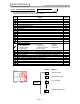
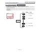
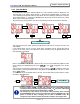
6.3.5 Press Result Display Mode
The following is displayed on the screen in the Press Result Display Mode.
The [D-NO] changes by pressing the [↑] and [↓] buttons.
D-NO DATA UNIT
_0 Peak Load Value(Judgment Load Value) KN
_1 Final Distance Value mm
_2 (Not Used) 1
s
t
Load Rate Value KN/mm
_3 (Not Used) 2
n
d
Load Rate Value KN/mm
_4 1
s
t
Region Operating Time Sec
_5 Final Region Operating Time Sec
_6 Cycle Time Sec
_7 Operation Mode Number
_8 Thermal value at Operation End (abnormal occurs if greater than 100)
_9 Lower 4 digits of final distance value (v1.96 or later)
-0 Press Method Number
-1 Step
-2 Distance when Press Speed Load was Detected (v1.96 or later) mm
-3 Self Check ON: performed OFF: not performed
-4 Speed when Speed Change Load was Detected (v1.96 or later) mm/sec
-5
Cause of press stop
0: Reset/No Data/After manual operation 1: Abnormal
2: BYPASS signal 3: STOP signal 4: REJECT
5: ACCEPT signal 6: START signal OFF * 7: CW signal *
8: CCW signal * *(v1.96 or later)
-6 Load Judgment Ld (Blank=Accept, H=High Reject, L=Low Reject)
-7 Distance Judgment dS (Blank=Accept, H=High Reject, L=Low Reject)
-8 Load Rate Judgment rt (Blank=Acc., H=High Rej., L=Low Rej., Z=1
s
t
Zone)
-9 Time Judgment Γi (1
ST
, 2
ND
)(Blank=Accept, H=High Reject)
=0 (Not Used) 1
ST
Load Rate Area Increment Load KN
=1 (Not Used) 2
ND
Load Rate Area Increment Load KN
=2 (Not Used) 1
ST
Final Load KN
=3 (Not Used) 1
ST
Peak Load KN
=4 Final Load Value KN
=5 Distance at Peak Load (judgment load) mm
「D-NO」 「DATA」
Peak load value
Final Distance value
1ST Load Rate
Distance at Peak Load
D-NO:left side figure
0
1
2
5
[↑] / [↓]
buttons