Chapter 6: System Operation PAGE 6 - 1
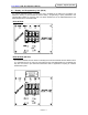
Chapter 6: System Operation enFORCE SAN Unit Operation Manual 6.1 Display and Programming Unit (DP*S) An optional detachable display / programming unit is available for the SAN Unit. The display unit allows the viewing of press results as well as viewing / programming of press parameters if the optional DSP software is not being used. The DP1S & DP2S are for the SAN3-24S/40S and the DP3S & DP4S are for the SAN3-120S.
Chapter 6: System Operation enFORCE SAN Unit Operation Manual 6.1.1 DP2S & DP4S Serial Connection Connector: DB-9P (Male) Mating Connector: DB-9S (Female) PIN No. Signal 1 Signal Description Not Used 2 RXD Not Used 3 TXD Output data for printer 4 DTR ON output (always) 5 GND Signal ground 6 Not Used 7 RTS ON output (always) 8 CTS Connects to DTR signals such as printers 9 Not Used The CTS signal needs to be activated in order for the press data to be output.
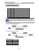
Chapter 6: System Operation enFORCE SAN Unit Operation Manual 6.1.2 RS-232C Output Data Result data is output every time the operation is finished. The result output is possible for each unit that has a SAN –DP2S/SP4S installed. Use SAN –IF unit if you want to output multiple results.
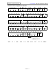
Chapter 6: System Operation enFORCE SAN Unit Operation Manual Data format when the judgment is a REJECT 1 2 3 4 COUNT Number 30H 30H 30H 31H 0 0 0 1 17 31H 1 33 20H 18 19 20 PEAK LOAD 32H 2EH 33H 2 34 35 36 FINAL LOAD 31H 2EH 32H 1 49 . 3 50 5 6 7 8 20H 20H 20H 20H 21 22 23 24 Judg ment 34H 20H 20H 20H 4 37 38 39 40 33H 20H 20H 20H 25 32H 2EH 33H 4 42 . 30H 2EH 31H 20H 31H 20H 20H . 1 . 2 46 47 48 Judg ment 33H 20H 20H 20H 3 Z 62 63 64 Judg ment 30H
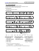
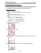
Chapter 6: System Operation enFORCE SAN Unit Operation Manual 6.2 Function of Display and Operating Panel Manual Operation Buttons [START]: Cycle START Button Pressing this button initiates the press cycle. The press will perform the operation as defined in the active parameter while pressing. This button must be held until the press cycle ends. If the button is released in the middle of the operation, the press will stop and, if programmed to do so, will return.
Chapter 6: System Operation enFORCE SAN Unit Operation Manual 6.3 RUN Status Mode Operating Instruction The enFORCE System has two operational states which are selected with the RUN/BYPASS switch on the front of the SAN Unit or by the PLC Bypass input. When the RUN/BYPASS switch is in the RUN position or when the PLC Bypass input is low (OFF), the unit is in RUN status. In the RUN status, press results, abnormalities and preset values are displayed. 6.3.
Chapter 6: System Operation enFORCE SAN Unit Operation Manual 6.3.2 Mode Change Three display modes can be selected while in the RUN state by pressing the [MODE] button. In addition, the values of each mode can be scrolled through by pressing the [↑] and [↓] buttons. When the unit powers on, the display defaults to the Real Time Display Mode. When the press cycle starts, the display switches to the Press Condition Display until the end of cycle.
Chapter 6: System Operation 6.3.3 enFORCE SAN Unit Operation Manual RUN Status Key Operation Selecting [Real Time Display Mode], [Press Result Display Mode] and [Parameter Display Mode] is possible by pressing the [MODE] button. When the press is operating, the [Press Condition Display] is displayed.
Chapter 6: System Operation enFORCE SAN Unit Operation Manual 6.3.4 D-NO: 1 figure Real Time Display Mode The following data is displayed on the screen in the Real Time Display Mode. The [D-NO] changes by pressing the [↑] and [↓] buttons. D-NO 0 1 2 DATA Load value display Displays present load applied on the load cell in real time. Load voltage value display Displays present load signal voltage applied on the load cell in real time.
Chapter 6: System Operation 6.3.5 enFORCE SAN Unit Operation Manual Press Result Display Mode D-NO:left side figure The following is displayed on the screen in the Press Result Display Mode. The [D-NO] changes by pressing the [↑] and [↓] buttons.
Chapter 6: System Operation enFORCE SAN Unit Operation Manual 6.3.6 Parameter Display Mode D-NO: 2 figure display The following data is displayed on the screen in the Parameter Display Mode. By pressing the [↑] and [↓] buttons, the [D-NO] changes and the value of the data number is displayed in the [DATA] area. If [↓] is pressed at the first data number of each parameter number, [PARM] parameter number will increment by 1.
Chapter 6: System Operation 6.3.7 enFORCE SAN Unit Operation Manual Operating Condition Display Speed conditions are shown on the display when in operation.
Chapter 6: System Operation enFORCE SAN Unit Operation Manual 6.3.
Chapter 6: System Operation enFORCE SAN Unit Operation Manual 6.4 BYPASS Mode Operating Instruction When the RUN/BYPASS switch is moved to the BYPASS position or when a Bypass signal is received from a PLC the BYPASS led will blink and the unit will be in the BYPASS state. In this state, the Press Unit number (U.01 to 32) is displayed on the screen. 6.4.
Chapter 6: System Operation enFORCE SAN Unit Operation Manual 6.4.2 Data Edit Mode Immediately after entering the “Data Edit Mode”, the cursor (blinking number) is displayed in the left most digit on the “DATA” display (DATA ①). Each time the [MODE] button is pressed, the cursor (blinking character) will shift to the right. When the cursor (blinking character) is in the right most position (DATA ④), pressing the [MODE] button will change the mode back to the “Setup Mode” (without saving any changes).
Chapter 6: System Operation 6.4.3 enFORCE SAN Unit Operation Manual Parameter Copying To speed data entry, it may be beneficial to copy from one parameter set to another parameter set. This is especially convenient in the case where minor changes must be made to parameters sharing common data.
Chapter 6: System Operation enFORCE SAN Unit Operation Manual 6.4.4 Data Number Definitions Organization of Parameter This system is capable of storing up to 32 different parameters for pressing. System Parameter (Parameter 0) The common settings used for Parameters 1 to 32 Load Unit [KN] Bank Select Enable SP Version Manual Speed Preamp Version Tool Type No Load Current Special Settings, etc.
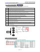
Chapter 6: System Operation enFORCE SAN Unit Operation Manual Data Number Conversion Table Item System Tool Data Tool Type Load Distance Special Option Time Speed Special Setting Parameter Number PARM 00 00 00 00 00 00 00 00 00 00 00 00 00 00 00 00 00 00 00 00 00 00 01~32 01~32 01~32 01~32 01~32 01~32 01~32 01~32 01~32 01~32 01~32 01~32 01~32 01~32 01~32 01~32 01~32 01~32 01~32 01~32 01~32 01~32 01~32 01~32 01~32 01~32 01~32 01~32 01~32 01~32 01~32 01~32 Data Number DNo 00 01 02 03 0
Chapter 6: System Operation enFORCE SAN Unit Operation Manual 6.4.4.1 System Parameter: Parameter Number 0 0 ¾ Data Number 0 0 Load Unit Load Unit 0: KN 1: KLBS 2: METRIC TON ¾ Data Number 0 1 S P Version (Read only except for parameter copy function) This is the Unit Software Version. No changes can be made. However, the [DATA] fields are made available for Parameter Copying.
Chapter 6: System Operation ¾ Data number 0 8 □ □ □ enFORCE SAN Unit Operation Manual Home Position Sensor Availability/PLC Bank Select Enable □ 0: No Home Position sensor (Default) 1: Home position sensor attached (on presses 10 ton and larger) 2: Bank Select enable (enable output signal banks 2 & 3) 0: Enable Distance High Limit Stop (Default) 1: Disable Distance High Limit Stop 0: 0.1mm distance sampling (Default) 1: 0.01mm distance sampling 2: 0.
Chapter 6: System Operation enFORCE SAN Unit Operation Manual ¾ Data Number 0 B Approach Distance Limit/Load Cell Availability This data field sets the maximum approach distance and availability of the load cell. □ □ □ □ Load Cell Availability 0: With Load Cell (Default) 1: Without Load Cell Approach Distance Limit (Default = 000) If you set 200, the approach distance will be up to 200mm. *Example: If the load transducer is used and the approach distance limit is 200mm, the setting will be 2000.
Chapter 6: System Operation enFORCE SAN Unit Operation Manual ¾ Data Number 2 0 Tool Number The connected tool number is set from the following tool table. Tool Number 30 44 31 19 32 33 43 27 34 42 35 40 41 37 38 39 09 13 14 16 17 47 80 Tool Number Maximum Load [KN] DPT-021R1-**F 1.96 DPT-021R2A-**F 1.96 DPT-051R2A-**F 4.90 DPT-051R3-**F 4.90 DPT-101R3-**F 9.81 DPT-151R3-**F 14.70 DPT-201R3-**F 19.60 DPT-231R3-**F 22.60 DPT-301R4-**F 29.40 DPT-301R4H-**F 29.40 DPT-501R4-**F 49.00 DPT-501R4H-**F 49.
Chapter 6: System Operation enFORCE SAN Unit Operation Manual 6.4.4.2 Work Parameters: Parameter Number 0 1 to 3 2 Load Settings Time Settings Special Settings Distance Settings Speed Settings ¾ Data Number 0 0 Press Mode(Press Method+Judgment Operation+ Return Operation) This data field will set the Press Method, Judgment Operation and Return Operation.
Chapter 6: System Operation enFORCE SAN Unit Operation Manual Press Methods ♦ Load Control (Method 0) Upon start of cycle, the press will operate until it achieves [13: Target Load]. During the press cycle, checks are performed for “Interference Check” / “Part Check”, Load and Distance. If any of these values are compromised, the press will stop and return as programmed. (See corresponding sections for Interference Check and Part Check explanations.
Chapter 6: System Operation enFORCE SAN Unit Operation Manual ♦ Distance Control (Method 1) Upon start of cycle, the press will operate until it achieves [22: Target Distance]. During the press cycle, checks are performed for “Interference Check” / “Part Check”, Load and Distance. If any of these values are compromised, the press will stop and return as programmed. (See corresponding sections for Interference Check and Part Check explanations.
Chapter 6: System Operation enFORCE SAN Unit Operation Manual ♦ Specified Point Load Judgment (Method 2 – Type 1) This Load Control press method allows judgment of a load (PS) at a given distance [13: Target Distance]. Type 1 Control is active if [22: Target Distance] is set to a number other than 0. Upon start of cycle, the press will operate until it achieves [13: Target Load]. During the press cycle, checks are performed for “Interference Check” / “Part Check”, Load and Distance.
Chapter 6: System Operation enFORCE SAN Unit Operation Manual ♦ Load Rise Detection (Method 2 – Type 2) This Load Control press method allows judgment of a distance (DS) at a given load [18: Detection Start Load] and press rate [33: Load Rate Change]. Type 2 Control is active if [22: Target Distance] is set to 0. Upon start of cycle, the press will operate until it achieves [13: Target Load].
Chapter 6: System Operation enFORCE SAN Unit Operation Manual ♦ Time Controlled Press (Method 3) This Load Control press method allows a pressing operation to be performed based off of a given time [42: Press Time]. Upon start of cycle, the press will operate until it achieves [13: Target Load].
Chapter 6: System Operation enFORCE SAN Unit Operation Manual ♦ Load Drop Detection (Method 4) This Load Control press method allows judgment of a load “drop off” or yielding point [63: Load Change]. Upon start of cycle, the press will operate until it achieves [13: Target Load]. During the press cycle, as soon as [18: Detection Start Load] is achieved, the press will begin looking for a yield in press force [63: Load Change].
Chapter 6: System Operation enFORCE SAN Unit Operation Manual ♦ Specified Range Peak Load Judgment (Method 5) This Load Control press method allows judgment of a peak load (PS) and judgment of the final distance (DS). Upon start of cycle, the press will operate until it achieves [13: Target Load]. During the press cycle, as soon as [18: Detection Start Load] is achieved, the press will begin looking for a peak in press force (PS).
Chapter 6: System Operation enFORCE SAN Unit Operation Manual ♦ Load Drop Detection – Point Stop (Method 6) This Load Control press method is similar to Method 3 (Load Drop Detection) except, once [63: Load Change] has been detected, the press will stop. The press will attempt to detect this value until it reaches [13: Target Load]. During the press cycle, checks are performed for “Interference Check” / “Part Check”, Load and Distance.
Chapter 6: System Operation enFORCE SAN Unit Operation Manual ♦ Distance Control with Load Limit (Method 7) Upon start of cycle, the press will operate until it achieves [22: Target Distance]. During the press cycle, after achieving [13: Target Load], the press rate will be current controlled to hold [13: Target Load] until [22: Target Distance] is reached. During the press cycle, checks are performed for “Interference Check” / “Part Check”, Load and Distance.
Chapter 6: System Operation enFORCE SAN Unit Operation Manual Judgment Operation Final Load Low Limit Judgment Disable [ 0 ] Judgment of a “Low Load” condition at the end of the press cycle will not be reported. All other judgments will be reported. Final Load Low Limit Judgment Enable [ 1 ] Judgment of a “Low Load” condition at the end of the press cycle will be reported. All other judgments will be reported. Part Check + Final Load Low Judgment [ 3 ] All programmed judgments will be performed.
Chapter 6: System Operation enFORCE SAN Unit Operation Manual Return Operation Return After both an ACCEPT or REJECT judgment the load will be released, then the press will move to the position set in [62: Job Start Position]. [ACCEPT] Return, [REJECT] No Return When the judgment is an ACCEPT, the press will move to the position set in [62: Job Start Position]. When the judgment is a REJECT, the press will stop and the load will be released.
Chapter 6: System Operation enFORCE SAN Unit Operation Manual ¾ Data Number 10 - Calibration Load The tool load value is set automatically when the tool type is selected. However, when depending on the application characteristics or applications which attach weighted fixtures on the end of the press ram, the value of the applied load and the load displayed by the SAN Unit may be mismatched.
Chapter 6: System Operation enFORCE SAN Unit Operation Manual ¾ Data Number 13 - Target Load In Load Control Methods, this is the target load value. (Example: If Target Load is 10KN, press will attempt to operate until 10KN is achieved.) A setting is possible from 0 to 105% of full-scale value. ¾ Data Number 14 – Press Speed Start Load The load value at which the speed of the press will change to [53: Press Speed]. A setting is possible from 0 to 105% of full-scale value.
Chapter 6: System Operation enFORCE SAN Unit Operation Manual Interference Check ¾ Data Number 15 - Interference Check Load (Part Check Load High) ¾ Data Number 23 - Interference Check Distance (Part Check Distance) These two settings may be used together to detect foreign substances (early load). If the press senses [15: Interference Check Load / Part Check Load High] before exceeding [23: Interference Check Distance / Part Check Distance], a “1ST Zone” reject will occur and press operation will stop.
Chapter 6: System Operation enFORCE SAN Unit Operation Manual ¾ Data Number 18 - Detection Start Load (Methods 2-2, 4, 5 and 6) The load at which the press will begin looking for the given values to determine judgment. A setting is possible from 0 to 105% of full-scale value. *This is also the measurement start load for Rate 2. ¾ Data Number 18 - Time Start Load (Method 3) The load at which the press begins measuring [42: Press Time].
Chapter 6: System Operation enFORCE SAN Unit Operation Manual ¾ Data Number 30 - Advance Position ON Distance (Data number OA set to [1~9]xxx) ¾ Data Number 31 - Advance Position OFF Distance (Data number OA set to [1~9]xxx) When Parameter 00, D-No. 0A (Option Setting) is set to a number other than zero, these settings control the “On” and “Off” of the Timing Signal while the press is advancing.
Chapter 6: System Operation enFORCE SAN Unit Operation Manual ¾ Data Number 51 - Approach Speed (Recommended Setting: 0~Tool Max. Speed) Higher speed value used for the “no-load” portion of the press operation. The press will run at this speed until [60: Approach Distance], [24: Press Speed Start Distance] or [14: Press Speed Start Load] is reached. Begins after [40: Slow Start Time] has passed. ¾ Data Number 52 - Part Search Speed (Recommended Setting: 0~50mm/sec.
Chapter 6: System Operation enFORCE SAN Unit Operation Manual ¾ Data Number 61 - Load Hold Time The press will hold the [13: Target Load] or [22: Target Distance] for the amount of time set. If 999.9 (1 figure below the decimal) or 9999 (no decimal point) is set, Load Hold Time is set to no limitation. It finishes operating when the START signal goes OFF. If using the “Advanced” signal, a time must be set. The “Advanced” signal will stay on for this set time.
Chapter 6: System Operation enFORCE SAN Unit Operation Manual Distance Offset Setup Example This example describes how the system should be set up when using a 250mm stroke press and pressing to a Target Distance of 200.00mm (2 decimal place accuracy). 1.
Chapter 6: System Operation enFORCE SAN Unit Operation Manual Step Press Operation using the Time Controlled Press Method A Step Press is a press operation that is done in multiple phases using multiple parameters. This operation works best when used in conjunction with the “Keep Load” Return Operation. For best results set up as follows: For a smooth curve, set [18: Time Start Load] equal to the previous step’s [13: Target Load]. Turn On the Self Check Off signal before starting each cycle.
Chapter 6: System Operation enFORCE SAN Unit Operation Manual 6.5 Setting Up a Parameter for Returning It is recommended that, if the return of the press is done with a parameter, use Distance Control. However, if Target Distance is set to 0 without a return operation, the press will reject because the Distance Low value is zero (a value less than zero is not possible). Refer to the following for setting up a Return Parameter. Adjustments can be made according to the individual application.
Chapter 6: System Operation enFORCE SAN Unit Operation Manual 6.5 External LVDT Sensor In applications which require the use of an external sensor to measure when actual part contact is made and THEN determine what the final press distance would be, the use of an external LVDT is required. The enFORCE System allows external distance data to be input from an LVDT controller via an RS232 connection.