
User guide


enFORCE DSP1500 Main Unit Hardware Manual
(Rev. 4.0) PAGE 5 - 68
Chapter 5: Control Interfaces
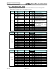
5.11.1 Component Descriptions
Fieldbus Interface Connections
Pin Signal Note
1 TD+
2 TD-
3 RD+
4 -
Normally left unused; to ensure signal integrity, these pins are tied
together and terminated to PE via a filter circuit in the module.
5 -
6 RD-
7 - Normally left unused; to ensure signal integrity, these pins are tied
together and terminated to PE via a filter circuit in the module.
8 -
Configuration Switches
These switches specify the binary value of the last byte of the IP
Address as specified in the following illustration:
192.168.0.42
These switches must be set before power is on and cannot be
changed during operation.
If these switches are set to 0 (zero), and no settings have been
specified by the application during startup, the module will use the
settings stored in the system file ‘ethcfg.cfg’. If this file is missing, the
module will attempt to retrieve the settings via DHCP or HICP for 30
seconds. If no configuration has been received within this period, the
module will halt and indicate an error on the Status LEDs.
Status LEDs
LED State Description
1 - Link
Off No Link Established
On Link Established
2 - Module Status
Off Not Powered / Not Online
Green solid Controlled by scanner in run state
Green flashing Not configured or scanner in idle state
Red solid
A major unrecoverable fault has been
detected.
Red flashing
A minor recoverable fault has been
detected.
3 - Network Status
Off
No power to device or no IP address
has been set.
Green solid
Online. One or more connections
established.
Green flashing Data size bigger than configured.
Red solid Duplicate IP address. Fatal error.
Red flashing One or more connections timed out.
Green / Red Self test in progress
4 - Activity Green
Flashes each time a packet is
transmitted or received.
1
2
3
4