
Brochure


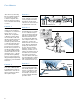


This figure shows an RP device
during a backsiphonage con-
dition. If you will notice, both
checks are closed tight and
the pressure differential relief
valve is discharging to atmo-
sphere. This is due to the fact
that the relief valve is designed
to maintain a lower pressure
in the zone between the two
check valves than the supply
pressure.
In this figure of an RP device,
there is a backpressure con-
dition. The second check is
fouled with a piece of pipe
scale which permits the higher
pressure to flow back into
the zone. Here the relief valve
discharges the water to atmo-
sphere maintaining the pres-
sure in the zone lower than the
supply pressure.
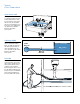
In this view of a pressure
vacuum breaker, a backsiphon-
age condition has caused the
check to close against its seat
and the air-inlet has opened so
that the pressure in the body
of the device is atmospheric. If
the check was fouled by some
foreign material, only air would
be pulled back into the domes-
tic supply system instead of the
non-potable water downstream
of the device.
In this view of a double check
valve, there is backpressure
from a source downstream
which has caused the second
check to close tightly against
this reverse pressure. The first
check has closed tightly by
itself, thus giving two barriers
against the backflow condition.
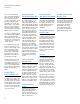
How Backflow Prevention
Devices Work
In this picture of an atmospheric
vacuum breaker, a backsiphon-
age condition exists. This condi-
tion has caused the check-float
to drop away from the air-inlet
and seat on the check seat,
which prevents the non-potable
water from being backsiphoned.
If the check-float did not seat
properly, again only air would
be sucked back into the domes-
tic water system.
97psi
100psi
105psi
100psi
105psi
80psi
92psi
7