
Owner's manual
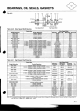
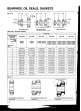
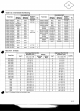
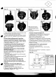


Fig. A-12 Fig. A-13 Fig. A-1
4
Fig. A-15
Fig. A-16
I
Fig. A-17
Note:
lnsert second disc with
number facing slow speed side,
exactly
180"
opposed to number
on first disc.
Note:
Set disc wi
slow speed side.
b. Apply grease to the raceway of the eccentric on the
disc. Fix the rollers and set disc in place.
c. Insert the spacer ring and set second disc in such a
way that mark is
180" opposed to mark on the bottom
disc.
Eccentric Bearing Replacement Precautions
The eccentric bearings are specially designed for in-
stallation on
SM-CYCLOn Reducers. They are special
roller bearings without outer raceways (refer to the list
of bearings on pages A-1
2
-
A-1
3).
It is necessary to insert replacement bearings with
numbered surfaces of the inner raceways facing
outward. Note that incorrect insertion of the bearings
(i.e., insertion of bearings with numbered surfaces
inside) causes trouble.
Disassembly and Assembly of Sizes 6060-6095
SM-CYCLOa Reducers
Small sizes 6060-6095 have a single disc system, so
they differ in construction from larger sizes in the
following ways:
1.
A balance weight is provided in lieu of the two-disc
system. Refer to figure
A-1 8.
2.
The balance weight must be positioned exactly 180"
as opposed to that of the eccentric.
3.
There are no end plates on either side of the
eccentric. In all other respects, 6060-6095 have
exactly the same construction as the larger sizes.
Follow the instructions given under "Disassembly and
Assembly".
Disassembly Of Output Side (6060-612H)
1.
With casing supported, tap output shaft until it is
disengaged from casing.
2.
Remove bearing
"A"
by using pulling tool.
3.
Replace all bearings, gaskets and seals when
reassembling. (Pages
A-1 1
-
A-1
3).
Assembly
Of Output Side (6060-612H)
1.
Assemble the
"B
bearing (Part No. 1-03) on the slow
speed shaft (Part No. 1-01). Heating of
"B"
bearing is
recommended for easier assembly.
Note:
Do not exceed temperature of 200°F.
2.
Assemble the casing (Part No. 26) over the slow speed
shaft (Part No. 1
-01), being sure to maintain
"X
(Fig. A-1 8).
3.
Carefully tap bearing
"A
(Part No. 1-02) onto the slow
speed shaft (Part No. 1-01) until the bearing is flush with the
shoulder of the casing.
4.
Place the collar (Part No. 1 -04H) onto the slow
speed shaft (Part No. 1-01). Heating the collar is
recommended for easier assembly.
5.
lnsert the oil seal (Part No. 18), lip in, into the casing
(Part No. 26).
Note:
Measure for dimension
"X
preferably in
3
places to
insure proper spacing.
Fig. A-18
X
Dimension (inches)
Frame
Size Dimension
6070/75 0.042
k
0.007
6090195 0.046
t
0.007
Ooio5 0.046
k
0.007
61
10/15/20/ 0.042
0,007
25,612H