
Owner's manual


-
-
-
E
DISASSEMBLYIASSEMBLY
Disassembly
SM-CYCLOQ Reducers are designed to provide
8.
Remove the spacer ring (2-05).
maximum ease when disassembing and reassembling;
9.
The eccentric (3-04) can be removed from .the
they require no special maintenance skills.
input shaft (3-01) after taking out the retaining ring
1.
Remove the complete SM-CYCLOm Reducer with
(3-10) and the inner bearing raceway (Figs. A-15,
adaptor (motorized type) from the driven machine.
A-1 6).
2.
Remove the plug at the bottom of the oil gauge to
Note:
In certa.in sizes, the eccentric bearings are
drain all oil from the unit.
roller bearings without a retainer. Remove bearings of
the top disc before proceeding with the next step.
3.
Remove the cooling fan cover and fan from those
Speed Reducers (not motorized) equipped with a
10.
Take out the second disc located on the motor
cooling fan, and stand the unit on a solid base with its
side. (Also remove second disc bearings and
high speed shaft side down. Remove the through bolts
eccentric with inner bearing raceway if required.)
for the high speed end shield, ring gear housing, and
11.
Remove the ring gear housing (2-01).
lift the slow speed side, thus separating the unit into
12.
Follow these steps to remove the slow speed
two parts so that the inner mechanism can be removed
shaft (1-01) with its bearings from the casing (26): (a)
(Figs. A-1 2
-
A1 7).
Remove the horizontal oil seal housing (25). (b) With
Note:
If the reducer is motorized (C-adaptor and
a wooden or hard rubber mallet, rap the inner end of
coupling) remove the motor and coupling before
the slow speed shaft to expose the retaining ring*
following the procedure outlined above. As a final step,
from the outer raceway of the bearing. (c) Remove
remove the adaptor and cooling fan.
the retaining ring. (d) Rap the outer end of the slow
speed shaft with a wooden or hard rubber mallet, and
4.
If the unit will not separate easily, gently drive a
remove it from the casing.
wedge at the line
X
shown in Fig. A-1 on page A-3 (if
13.
The high speed shaft (3-01) with bearings is
this produces a burr, be sure to remove it before
removed from the high speed shaft end shield
(8)
by
reassembly).
tapping the shaft end after first taking off the retaining
5.
To lift the slow speed side, attach an eyebolt to the
ring (3-1 1).
tapped hole on the end of the slow speed shaft and
14.
The cycloid disc is made from heat-treated
use a hoist or chain block (Fig. A-1 2).
bearing steel and the spacer ring is cast iron. Take
6.
Take out the slow speed shaft rollers, item 1-06,
care not to strike them together while handling.
page A-3 (Fig. A-13). Check the slow speed shaft pins
The above instructions cover complete disassembly.
(1-01) to see whether any rollers have adhered to
In ordinary cases, however, only the removal of the
them.
cycloid discs and the eccentric, and removal of the
7.
Using both hands, lift out the top cycloid disc (2-04)
slow speed shaft from the slow speed end cap is
on the slow speed side (Fig. A-14).
necessary.
*Note:
Retaining ring is part of bearing A
(Part No. 1-02).
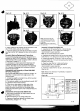
Assembly
SM-CYCLOQ Reducers are reassembled by reversing
4.
Insert the spacer (3-07) and then insert the
the disassembly procedure. Care must be taken to
eccentric with bearings by rapping with a wooden or
exclude dust or foreign matter from the moving parts,
hard rubber mallet (Fig. A-16).
and to see that gaskets are properly placed to make the
assembly oil-tight.
5.
lnsert the other spacer and the inner bearing
raceway. Secure them with the retaining ring
Following are some helpful points to remember when
(Fig. A-15).
assembling SM-CYCLOm Reducers.
6.
Set the spacer ring in place.
1.
Set the ring gear housing and insert the ring gear
7.
Insert top disc in such a way that the mark is
pins and rollers; then test-rotate the pins and rollers by
180"
opposed to the mark on the bottom disc
hand. (Apply grease liberally to the ring gear pins and
(Fig.
A-1
3).
rollers before they are inserted in grease lubricated
SM-CYCLOa Reducers.)
8.
lnsert slow speed shaft rollers (Fig. A-1 3).
9.
Put the slow speed shaft pins into the rollers (Fig.
2.
Cycloid discs are a matched pair. Each carries the
A-1 2). The above instructions are for
eccentric
same number stamped on one side of the disc.
bearings with retainer.
Following are the instructions
3.
Set the cycloid disc with the stamped nurr~ber face up
suggested for
roller bearings without retainer.
as shown in Fig. A-1 7.
a. First insert the eccentric with inner raceways of
bearings by rapping with a wooden or hard rubber
mallet.
A-14