
Owner's manual
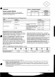
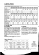
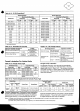
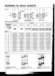
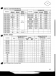
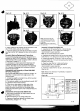
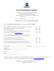


Table A-12. Oil Fill Quantities[l]
(
) with trochoid pump
Table A-13. Allowable Oil Viscosity
Maximum Allowable Viscosity
To Allow Easy Starting
Single Reduction
Forced Lubrication For Vertical Units
Table A-15. Plunger Pump Type
Frame Size
6130,6135
6140,
6145,614H
6160,6165,616H
61 70,6175
6180 6185
Double Reduction
Frame Size
6160DC, 6165DC
6170DC, 6175DC
6180DB, 6185DB
61 90DA, 61 95DA
6190DB 6195DB
Table A-14. Oil Change Interval
Mounting Configuration
Mounting Configuration
Small Size Pump
Plunger Pump Lubrication
The plunger pump (Fig.
A-2,
Part
#42)
is automatically
operated by a cam (Fig.
A-2,
Part
#40)
fitted on the slow
speed shaft (Fig.
A-2,
Part
#I-01).
The number of pumping
cam teeth required is in direct relation to the reduction ratio
and frame size. Please consult the factory for input speeds
other than standard.
Horizontal
Frame Size
6160,6165,6170,6175,
61 80,6185,6190,6195
6160DC, 6165DC, 6170DC,
6175DC, 6180DB, 6185DB,
61 90DA, 6195DA, 6190DB,
6195DB
Large Size Pump
Table A-16. Positive Displacement (Trochoid) Pump Type
U.S. gal.
0.18
0.18
0.37
0.50
0.66
Vertical
Horizontal
Operation Condition
Under Every Condition
Less Than 10
HourslDay
Operation
10
-
24 HourslDay
Operation
High Ambient Temperature,
High Humidity or
Atmosphere of Active Gas
Oil Change Interval
Ratio
See
Table A-5
See
Table A-6
Frame Size
6205,6215,6225,6235,
6245,6255,6265,6275
6205DA, 6205DB, 621 5DA,
6215DB, 6225DA, 6225DB,
6235DA, 6235DB,6245DA,
6245DB, 6255DA, 6255DB,
6265DA
Positive Displacement (Trochoid) Pump Lubrication
Forced oil lubrication is accomplished by using a positive motor be interlocked with the pump motor to avoid operation
displacement pump and motor that requires an additional without lubrication. The pump must be started
30
seconds
electric power source. It is recommended that the main
or longer before the main motor is operated.
liter
0.7
0.7
1.4
1.9
2.5
U.S. gal.
0.29
0.29
0.26
0.50
0.53
U.S. gal.
0.40
0.63
0.92
1.5
1.6
Vertical
Initial Oil Change
Subsequent Oil
Change
>
Ratio
See
Table A-5
See
Table A-6
hlntar.
I11
Dln~cn mncm ,It thn f~rtnnr fnr nil nl ~~ntitinc urhnn thn rnrlm nrnrlnn~rmntnr ic
mnm
mntnrl in In\, nthnr nnritinn nr ~nnln
liter
1.1
1.1
1
.O
1.9
2.0
liter
1.5
2.4
3.5
5.8
6.0
U.S. gal.
0.26
0.50
0.53
0.71
0.71
After 500 Hours of
Primary
Operation
Every 6 Months
Every 2,500 Hours
Every 1
-
3 Months
'."LU...
L
8
J
8
8UU-U 'V"i."'L L"C '"ULV'y
'V' V"
,,"CI"L"'Ci.
""8
'C"
L"F 'GU"UC"~F~'IIIVLVI
li.
1IIV"l
llGU
II I
-1
1)1
VLl
lGl
,,VIIII"I
I
"I
CII
IYIU.
[2] Consult the factory when using an inverter.
[3] A relief valve, pressure set at 42.7 psi (3 kgf/cm2), is a standard attachment on the trochoid pump.
liter
1
.O
1.9
2.0
2.7
2.7