
User Manual


Page 6 of 11 Rev
0
AIRWAVE TECHNOLOGIES INC.
4F, No.9 Industry E. 9
th
RD., Science-Based Industrial Park, Hsinchu, Taiwan, R.O.C. TEL : 886-3-5778099 Fax 886-3-5778199
www.airwave.com.tw
Copyright © 2008 by Airwave Technologies Inc. All Specification are subject to change without notice.
Date : 2008/12/3
Design Kit – 5.8GHz Wideband FM Receiver Module
Doc No :
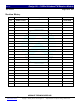
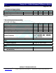
6. PIN descriptions:
PIN NAME Descriptions
01 VCC DC +5V power supply in
)
.
02 BYPASS Bypass capacitor.
03 GND Ground.
04 Audio_R Right sound signal output.
05 Audio_L Left sound signal output.
06 Video Video signal output.
07 B2 Channel select.
08 B1 Channel select.
09 B0 Channel select.
10 GND Ground.
11 RF IN RF received signal input
12 GND Ground
Channel selection are seven channels by Pin20, Pin19 and Pin 18 for dip sw mode As shown below:
Table1:
Pin07 Pin08 Pin09
B2 B1 B0
Descriptions
Receiver
Frequency
0 0 0 Pin 07, Pin 08, Pin 09 connect to GND. 5740MHz (CH1)
0 0 1 Pin 07 and Pin 08 connect to GND, Pin 09 OPEN. 5760MHz (CH2)
0 1 0 Pin 07 and Pin 09 connect to GND, Pin 08 OPEN. 5780MHz (CH3)
0 1 1 Pin 07 connect to GND, Pin 08 and Pin 09 OPEN. 5800MHz (CH4)
1 0 0 Pin 08 and Pin 09 connect to GND, Pin 07 OPEN. 5820MHz (CH5)
1 0 1 Pin 08 connect to GND, Pin 07 and Pin 09 OPEN. 5840MHz (CH6)
1 1 0 Pin 09 connect to GND, Pin 07 and Pin 08 OPEN. 5860MHz (CH7)