
Product Manual

13
A Product of Progress Mfg. Inc.
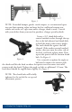
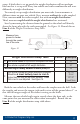
read a 1/2” x 4” bolt through the single hole of the outside and inside link
plates from the outside in. e head of the bolt should be against the outside
link plate with the threads to the inside. Slide a lock washer on, then thread a
nut onto end of bolt a few turns. Slide the link plates over the frame as shown
so that the L-bracket studs are facing outward. read the second bolt through
the link plate holes closest to the trailer frame with the head on the outside, and
thread the lock washer and nut onto it from the back side.
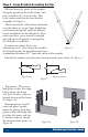
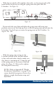
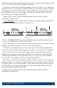
Pinch the inside and outside link plates tight to the trailer frame so that both
lay at against the frame. Inside link plates are sometimes slightly bowed. If this
is the case, the center of the bow should be placed toward the trailer frame so
that as they are tightened they atten out against the frame.
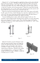
Continue holding them in place while you hand tighten both nuts. Use
wrenches to nish tightening the link plate bolts until they are snug, alternating
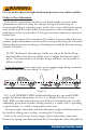
from top to bottom 1/2 turn at a time. ese should be torqued to 65ft-lbs.
Improper installation or under tightening may cause link plates to “walk” along
the frame. See Figure 9.
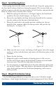
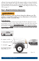
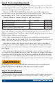
Slide the L-brackets onto the link plate studs
with the spring arm plate facing away from the
trailer. For the initial setup, leave two (2) holes
showing at the top above the studs and two
(2) below. See Figure 10. ey may need to be
adjusted up or down later. read on the nylock
nuts and tighten them - see Figure 10. When
weight distribution setup is complete, torque the
L-bracket nuts to 75ft-lbs.
Figure 9
Correct Incorrect
Figure 10