
Product Manual

12
FastwayTrailer.com
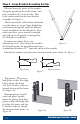
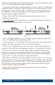
Step 4 - Sway Bracket Assembly Set Up:
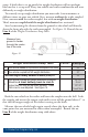
Measure from the center of the coupler
along the outside of the trailer frame, and
place a mark at 30” on both sides. is
is the center mark for the sway bracket
assembly. See Figure 6.
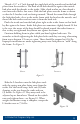
Check around the trailer frame and make
sure that there are no gas lines, brake lines,
or electrical wiring that could be aected
by the installation of the link plates. If so,
make sure these are re-routed or avoided
and will not be disrupted or damaged by
the link plate installation.
In some cases where there is an
obstruction at 30” that cannot be avoided,
the link plates may be moved forward up to
a minimum distance of 27” from the center of the coupler.
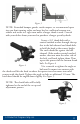
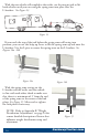
Identify the coupler style that most closely matches your trailer. See Figure 7.
Top-mount: Place your
link plates so that the single
hole is above the frame,
and the L-bracket studs are
toward the top of the frame.
See Figure 8a.
Bottom-mount: Install
your link plates ‘upside-
down’ by placing your link
plates so that the single hole
is below the frame, and the
L-bracket studs are toward
the bottom of the frame. See
Figure 8b.
27”-30”
Figure 6
Figure 8bFigure 8a
Top-mount Bottom-mount
Figure 7