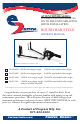
ATTENTION DEALERS: PLEASE PASS THIS MANUAL ON TO THE END USER AFTER HITCH INSTALLATION. ROUND BAR STYLE OWNER’S MANUAL Hitch ball not included except model 94-00-1061. Patented 94-00-0600 600 lb. max tongue weight 6,000 lb. max loaded trailer weight 94-00-0800 800 lb. max tongue weight 8,000 lb. max loaded trailer weight 94-00-1000 1,000 lb. max tongue weight 10,000 lb. max loaded trailer weight 94-00-1061 1,000 lb. max tongue weight 10,000 lb.
FastwayTrailer.
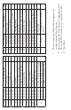
Item # Part Number 1 92-04-9208 2 93-04-9285 3 92-03-9205 4 93-02-5150 5 93-02-9270 6 93-02-5350 7 93-02-5200 8 92-04-9228 9 92-04-9290 10 92-00-6000 11 92-03-9700 94-02-0699 12* 94-02-0899 94-02-1099 Part Description Qty. L-Pin Clip 2 1/2” Nylock Nut 4 L-Pin 2 L-Bracket 2 1/2” x 4” Bolt - Grade 5 4 Studded Outside Link Plate 2 Inside Link Plate 2 1/2” Nut 4 1/2” Lock Washer 4 Snap-up Lever 1 5/8” Angle Set Bolt 1 6,000 lb. Spring Arm (single) 8,000 lb. Spring Arm (single) 2* 10,000 lb. Spring Arm (sngl.
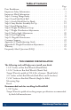
Table of Contents Page Parts Breakdown . . . . . . . . . . . . . . . . . . . . . . . . . . . 2-3 Important Safety Information . . . . . . . . . . . . . . . . . . . . . 5 Important Hitch Information . . . . . . . . . . . . . . . . . . . . . . 7 Step 1: Getting Things Ready . . . . . . . . . . . . . . . . . . . . . . 8 Step 2: Install the Hitch Ball . . . . . . . . . . . . . . . . . . . . . .
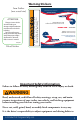
Warning Stickers Improper setup can cause severe injury or death. • Read and follow owner’s manual at all times. • Check for proper setup before towing. Head Sticker The e2™ hitch is a product of Progress Mfg. Inc. Meets V5 and SAE standards. E2RB_0911 Faster, Easier. Changes in tow vehicle & trailer loading can change weight distribution requirements and vehicle handling. For best performance check your hitch setup often. Verify that proper weight distribution is achieved. Refer to owner’s manual.
match towing conditions. The driver is responsible for their own safety and the safety of passengers. Never exceed the specified weight ratings for the trailer, tow vehicle, hitch, hitch ball, or any other towing equipment. No hitch setup guarantees that trailer sway will be altogether avoided. Always load trailer correctly. Follow trailer and tow vehicle manufacturer’s recommendations for placement and quantity of cargo. Always tow with a minimum tongue weight of 10% of the gross trailer weight.
CAUTION Do not loosen or remove any part of the hitch except the L-pins and L-pin clips while the hitch is under load. CAUTION Always secure tow vehicle and trailer with parking brake and wheel chocks before setting up or adjusting hitch. Disengage weight distribution before towing or backing the trailer where there is a significant transition in grade which puts excessive strain on the hitch, i.e. a flat street to a steep uphill driveway.
adjusted for your load, the e2 hitch can noticeably reduce sway through good weight distribution and the friction of Built-in Sway Control. Important Setup Information: These instructions are a guideline to aid in setting up your hitch. Every trailer and tow vehicle combination requires a different setup and adjustment because of factors like trailer weight and length, trailer loading, hitch weight, and tow vehicle suspension and wheelbase.
as they will be while traveling. This includes full propane tanks, fresh water tanks, and any other cargo (passengers & gear) the tow vehicle or trailer will carry, including ATVs for toy haulers. Tow vehicle “auto-level” systems should also be disabled or turned off. If your tow vehicle is equipped with air bags, we recommend that you inflate them to the pressure you are expecting to tow with before setting up the hitch.
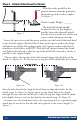
Step 3 - Attach Hitch Head to Shank: With the trailer parallel to the ground, measure from the ground to the inside top of the trailer coupler. See Figure 1. Trailer Coupler Height: _______ ?? The hitch ball should initially be placed as close to this height as possible. Insert the adjustable shank Figure 1 into the receiver on the tow vehicle and secure it with a hitch pin and clip. Insert the spacer rivet with the spacer washers into the back of the hitch head to pre-load the angle of the hitch head.
Figure 3 NOTE: Extended bumper guards, truck campers, or rear mounted spare tires can limit turning radius and may lead to a collision between tow vehicle and trailer in a tight turn unless a longer shank is used. Consult with your dealer about your need to purchase a longer specialty shank. Insert a 3/4” shank bolt with a conical toothed washer through the top slot in the bolt channel and shank hole to hold the head at the correct height. The teeth should be against the bolt channel.
”m / 27 24” min Measure from the center of the coupler along the outside of the trailer frame, and place a mark at 27” on both sides. This is the center mark for the sway bracket assembly. See Figure 6a. Check around the trailer frame and make sure that there are no gas lines, brake lines, or electrical wiring that could be affected by the installation of the link plates. If so, make sure these are re-routed or avoided and will not be disrupted or damaged by the link plate installation.
Identify the coupler style that most closely matches your trailer. See Figure 7. Top-mount: Place your link plates so that the single Top-mount Bottom-mount hole is above the frame, and Figure 7 the L-bracket studs are toward the top of the frame. See Figure 8a. Bottom-mount: Install your link plates ‘upsidedown’ by placing your link plates so that the single hole is below the frame, and the L-bracket studs are toward the bottom of the frame. See Figure 8b.
Slide the L-brackets onto the link plate studs with the spring arm plate facing away from the trailer. For the initial setup, leave two (2) holes showing at the top above the studs and two (2) below. They may need to be adjusted up or down later. Thread on the nylock nuts and tighten them. See Figure 10. When weight distribution setup is complete, torque the L-bracket nuts to 75 ft‑lbs.
different times on your tow vehicle. First, measure without the trailer coupled. Next, measure with the trailer coupled, but with no weight distribution. Third, measure coupled with the weight distribution bars tensioned. Start by measuring the distance from the ground to the wheel well directly above the front axle with the trailer uncoupled. See Figure 12. Record this on Line A of the Weight Distribution Setup Table. Measure from ground to fender through the centerline of the axle.
Figure 13 Figure 14a Figure 14b With the spring arms resting on the L-bracket and the trailer and tow vehicle in line with each other, check to make sure that there is a minimum of 3” from the end of the spring arms to the center of the link plates. See Figure 15. Move and re-tighten the link plates if necessary. NOTE: Refer to Appendix B “Weight Distribution Adjustments” on page 24 for a more detailed description of factors that influence weight distribution setup and adjustment.
Step 7 - Weight Distribution Adjustments WARNING Weight distribution is only one of many things that influence sway. The operator is responsible for making necessary adjustments to all contribut‑ ing factors in order to minimize sway.
WARNING Over or under adjusted weight distribution decreases tow vehicle stability. WARNING Under or Over Adjustment: If the hitch is transferring too little or too much weight, you must make adjustments to the hitch setup. For changes during the initial setup we recommend adding or removing spacer washers first to try and keep the spring arms parallel with the trailer frame. In our experience, this can improve the performance of the sway brackets.
vehicle forward. Remove the hitch head and add a spacer washer. Repeat step 6 and 7 to re-adjust and check weight distribution. If you have reached the maximum number of spacer washers, or if adjusting temporarily due to a change in vehicle loading, use the tongue jack to unload the spring arms. Raise the L-brackets 1 hole. Move the spring arms back over the L-brackets and retract the tongue jack. Re-measure the wheel wells and check for proper weight distribution.
Step 8 - Trailer Angle Adjustment: After achieving a good weight distribution setup you may need to adjust the attitude (angle) of the trailer. Step back and look at the trailer to see if the front appears to be tipped up or down excessively. Measure the FRONT and REAR of the trailer again at the same points you did when setting the trailer parallel to the ground in Step 1. Record these measurements on the Trailer Attitude Adjustment chart below. Find the difference between the highest and lowest heights.
attitude, tighten all of the nuts and bolts securely. With the weight distribution engaged, begin with the angle set bolt, and tighten it until it comes back into solid contact with the shank plus 1/4 turn. Uncouple the trailer, then tighten all other bolts and nuts to the proper torque specs. Tighten both 3/4” shank bolts to 250 ft‑lbs. torque.
configuration. With use, the spacer washers and rivet may compact slightly leaving a small gap between the angle set bolt and the shank. The bolt should be checked frequently when your hitch is new and re-tightened until it comes in contact with the shank, plus 1/4 turn. You will notice that over time the need to re-tighten the angle set bolt will diminish, but you should still check it regularly before each towing day as part of your hook-up routine. Store your hitch out of the weather when not in use.
Appendix A TROUBLE SHOOTING Problem Possible Cause Correction Trailer Sway Not enough Weight Distributed. Add spacer washer(s), or Raise LBrackets. Remember, trailer Light Tongue Weight sway is caused by the combined vehicle (tow vehicle/trailer) configuration or outside forces. If you are unImproperly Rated or sure what may be caus- Under-inflated Tires ing your sway issues, contact your dealer or a hitch specialist for assistance.
Appendix B Weight Distribution Adjustments: You should carefully consider the following items and their effects when setting up initially and when adjusting your hitch before each trip: • Vehicle wheel base: Shorter wheelbase vehicles react farther and faster than longer wheelbase vehicles to weight distribution adjustments. • Vehicle suspension: Soft suspensions, such as an SUV will react farther and faster to weight distribution adjustments than stiff suspensions like a 3/4 ton pickup.
Cargo carriers, bike racks, and second trailers attached to the rear bumper of a trailer add weight to the rear of the trailer that automatically subtracts tongue weight. We recommend that you do not add weight of any form to the rear bumper of your trailer. We also recommend that you do not tow a 2nd trailer under any circumstance. • Trailer coupled attitude: Attitude refers to the angle that the trailer is tipped to.
FAQ Q: A: How often do I need to adjust the angle set bolt? This bolt only needs to be tightened if you notice a gap between the end of it and the hitch shank. It should be checked more frequently when your hitch is new. Include it as part of your routine when preparing to tow. See Step 10 - Regular Maintenance. Q: A: Can I back up with the hitch hooked up and weight distribution engaged? Yes, you don’t have to remove the spring arms like you would an add-on sway bar to back up.
NOTES _____________________________________________________________ _____________________________________________________________ _____________________________________________________________ _____________________________________________________________ _____________________________________________________________ _____________________________________________________________ _____________________________________________________________ _____________________________________________________________ __________
Other Great Fastway Towing Accessories The Fastway® ONEstep™ is the fastest and easiest positive locking tandem axle wheel chock available! Simply step down on the scissor arms to firmly lock your trailer in place, and lean the cable against the tire. To remove, pull up on the cable and the chock slides right out, even if the trailer has shifted slightly. Center pin design quickly adjusts the chock from 16” to 24” to fit most tandem axle trailers.