
Product Manual


12
FastwayTrailer.com
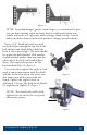
Step 4 - Sway Bracket Assembly Set Up:
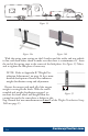
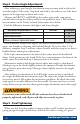
Measure from the center of the coupler
along the outside of the trailer frame, and
place a mark at 27” on both sides. is
is the center mark for the sway bracket
assembly. See Figure 6a.
Check around the trailer frame and make
sure that there are no gas lines, brake lines,
or electrical wiring that could be aected
by the installation of the link plates. If so,
make sure these are re-routed or avoided
and will not be disrupted or damaged by
the link plate installation.
In some cases where there is an
obstruction at 27” that cannot be avoided,
the link plates may be moved forward up to
a minimum distance of 24” from the center of the coupler.
NOTE: For trailers with an obstruction
that does not allow installation at 24”-27”;
if the tongue weight of the trailer is less
than 800 lbs., the brackets may be moved
forward down to a minimum of 20” on
center. Be aware that moving the bracket
assembly forward can alter the stiness of
the ride and the weight distribution set-up.
Re-adjust the setup as necessary to get
good weight distribution.
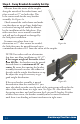
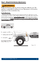
If the sway bracket assembly is moved
forward more than the standard 24” you
must also check to make sure the ends of the spring arms will not hit the
sides of the trailer frame in a tight turn. SeeFigure6b. Also check that
the spring arm does not bind between the L-pin and L-bracket. If either
of these issues occur, the bracket assembly must be moved backward
until there is no binding or frame interference in tight turns.
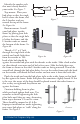
24” min / 27” max
Figure 6a
Figure 6b