
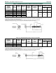
Dimensions Guide


ESR-1078
|
Most Widely Accepted and Trusted Page 6 of 8
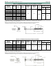
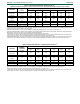
TABLE 2—REFERENCE WITHDRAWAL DESIGN VALUES (W)
1,2,3
[Reference withdrawal design values (W) are in pounds per inch of thread penetration into side grain of main member]
FASTENER
THREAD LENGTH,
L
4
(inches)
W (lbf./in.) FOR SPECIFIC GRAVITIES OF:
0.57
0.55
0.5
0.46
0.43
0.42
OlyLog/
TimberLOK
1.25 or 2.0
270
260
220
200
180
170
HeadLOK
2.0
290
270
230
200
180
170
LedgerLOK/
LogHog
2.0 or 3.0
330
310
270
240
220
210
TrussLOK
1
1
/
2
—
—
180
—
—
—
TrussLOK-Z
1
1
/
4
290
270
220
180
160
150
ThruLOK
(5)
NA
(6)
1140
(6)
1060
(6)
900
(6)
780
(6)
700
(6)
680
(6)
For SI: 1 inch = 25.4 mm, 1 lbf/in = 175 N/m.
1
Tabulated reference withdrawal design values, W, apply to fasteners driven into the side grain of the main member, such that the screws are oriented
perpendicular to the grain and loaded in direct withdrawal.
2
Reference withdrawal design values must be multiplied by all applicable adjustment factors, in accordance with Section 4.1.
3
Reference withdrawal design values are to be multiplied by the length of thread penetration into the main member, but must not exceed the head pull-
through design values given in Table 3. Threaded length includes the tapered tip.
4
See Tables 1A through 1F for thread lengths corresponding to specific fastener model numbers.
5
The ThruLOK must be used with the ThruLOK washer and nut (supplied with the fastener). The nut must be installed such that it is snug against the
main member, and at least
1
/
2
inch of the threaded portion of the shank (not including the tip) is within the nut.
6
Tabulated withdrawal values for the ThruLOK are based on the head pull-through design values given in Table 3, as these values will govern designs
in which the screw is subject to axial tension, where the ThruLOK is properly installed with the ThruLOK washer and nut (see footnote 5 above).
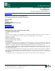
TABLE 3—REFERENCE HEAD PULL-THROUGH DESIGN VALUES (P)
1,2
FASTENER
MINIMUM SIDE
MEMBER
THICKNESS
(inches)
P (lbf) FOR SPECIFIC GRAVITIES OF:
0.57
0.55
0.5
0.46
0.43
0.42
OlyLog/
TimberLOK
1.5
220
200
160
130
110
110
HeadLOK
1.5
630
600
520
460
410
400
LedgerLOK/
LogHog
1.5
320
290
240
200
180
170
TrussLOK
1.5
—
—
260
—
—
—
TrussLOK-Z
1.5
370
330
250
200
170
160
ThruLOK
(3)
1.5
1140
(3)
1060
(3)
900
(3)
780
(3)
700
(3)
680
(3)
For SI: 1 inch = 25.4 mm, 1 pound = 4.448 kPa.
1
Reference head pull-through design values, P, must be multiplied by all applicable adjustment factors, in accordance with Section 4.1.
2
Design values apply to connections with minimum side member thicknesses, t
s
, as given above.
3
The ThruLOK must be used with the ThruLOK washer and nut (supplied with the fastener). The nut must be installed such that it is snug against the
main member, and at least
1
/
2
inch of the threaded portion of the shank (not including the tip) is within the nut.