
User's Manual

Liberator-V1000 User Manual Rev 04v05
Page 24 of 85 FBN Doc #: FBN-0125_04v05
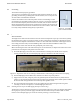
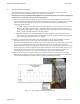
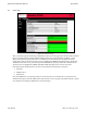
Figure 24 - (a) Horizontal (azimuth) adjustment screw (b) Vertical (elevation) adjustment screw
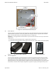
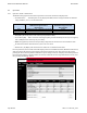
Figure 25 - (a) Locking the horizontal position (b) Locking the vertical position
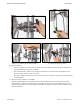
(b) Optical alignment
•
Place the alignment tool on the most accessible corner of the radio unit and ensure good visibility to the
opposite terminal by rotating the viewfinder.
•
Use a 6mm Allen-Key / T-Bar tool to orientate the bracket in to a position where the alignment scope
shows the target location is in the cross hairs.
•
Once this is completed correctly at both end, you will be able to measure a Voltage via the DC port (Power
Level Alignment)
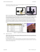
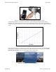
(c) Alignment using a voltmeter to read RSSI
Following optical alignment, an alignment based on the received power level of each terminal should be
performed. Use a voltmeter and cable with a female QMA connector to attach to the QMA connector on the
terminal of the procedure for optical alignment, and adjust the alignment bracket to obtain maximum voltage
from each terminal.