
User's Manual

Liberator-V1000 User Manual Rev 04v05
Page 20 of 85 FBN Doc #: FBN-0125_04v05
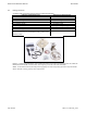
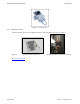
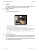
Figure 16 – V1000 Single-port Backhousing with Arrows indicating Polarization Direction
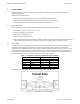
On Dual-port versions, the polarization is indicated by a pair of black dots on the front frame of the antenna
face, as shown below.
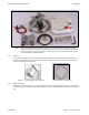
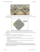
Figure 17 - V1000 Dual-port Backhousing with black dots indicating polarization direction
The terminal must be mounted on the bracket using the enclosed stainless steel screws (M6 x 12).
NOTE: Do not use zinc-plated screws as these will corrode and endanger link performance and safety to people
and equipment.
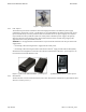
4.2.2 Terminal Installation – Configuration of Co-located Terminals
If radio terminals are sited together in a cluster, configure the links to minimise interference by:
Swapping Tx High / Low (Swap A and B terminals).
Swapping polarization (Rotate radio terminals by 90 degrees so that arrows are swapped vertical /
horizontal).
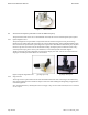
Using different frequencies (Choose from 3 non-overlapping channels on Single-port and 4 non-
overlapping channels on Dual-port).
Physically separating the terminals by at least 1 metre.
For dense networks, especially with multiple clusters terminating on a single building, it is advisable to
perform frequency planning prior to installation of the links: Fastback Networks have a planning tool to help
with this, or else an industry-standard tool such as Pathloss may be used. Fastback Networks can supply
Pathloss configuration files on request.